Eureka AIR delivers breakthrough ideas for toughest innovation challenges, trusted by R&D personnel around the world.

Microwave coupled plasma generating device with electromagnetic energy dual-excitation function

A technology for coupling plasma and electromagnetic energy, applied in the direction of plasma, electrical components, etc., can solve problems such as plasma torch flame disturbance, and achieve the effects of increasing electron density, improving utilization efficiency, and stabilizing shape

Pending Publication Date: 2020-08-11
JILIN UNIV
View PDF1 Cites 3 Cited by
  • Summary
  • Abstract
  • Description
  • Claims
  • Application Information

AI Technical Summary

Problems solved by technology

Although the problem of partial ionization of atmospheric components can be solved, the gas flow used as a shield will create new disturbances to the plasma torch

Method used


Image

  • Microwave coupled plasma generating device with electromagnetic energy dual-excitation function
  • Microwave coupled plasma generating device with electromagnetic energy dual-excitation function
  • Microwave coupled plasma generating device with electromagnetic energy dual-excitation function

Examples


Embodiment 1

[0035] Embodiment 1 permanent magnet method

[0036] see Figure 5 , an MCP generating device that uses a permanent magnet to generate magnetic field energy and has dual functions of electromagnetic energy. The device is mainly composed of a microwave coaxial resonant cavity part and a magnetic field generating part.

[0037] The microwave coaxial resonant cavity part includes outer conductor 1, microwave antenna 2, inner conductor 3, middle tube 4, inner tube 5, sample tube 6 and impedance matching cylinder 7; outer conductor 1, inner conductor 3, middle tube 4, inner tube 5. The sample tube 6 is nested and coaxial in sequence from outside to inside. The sample tube 6, inner tube 5, middle tube 4 and inner conductor 3 are flush at the outlet end face of the resonant cavity formed. The inner conductor 3 The outer surface and the inner surface of the outer conductor 1 jointly constitute the working body of the microwave coaxial resonant cavity. The characteristic impedance ran...

Embodiment 2

[0047] Embodiment 2 Excitation coil method

[0048] see Figure 5 , based on Embodiment 1, the excitation part provided by this embodiment is implemented by an excitation coil, and the microwave coaxial resonant cavity part is the same as that of Embodiment 1, and will not be repeated here.

[0049] The excitation lower part 8 , the excitation middle part 9 and the excitation upper part 10 are composed of three excitation coils.

[0050] The magnetic fields generated by the three excitation coils have the same direction and coincide with the central axis of the plasma.

[0051] The magnetic field intensity of the excitation lower part 8 and the excitation upper part 10 is the same and slightly greater than that of the excitation middle part 9, forming a saddle-shaped magnetic field with two ends slightly higher and the middle slightly lower, that is, a confining plasma torch with two ends approximately convergent The magnetic potential well of the flame makes it difficult fo...


PUM


Abstract

The invention discloses a microwave coupled plasma generating device with an electromagnetic energy dual excitation function, and belongs to the technical field of microwave energy application. The microwave coupled plasma generating device is composed of a microwave coaxial resonant cavity part and a magnetic field generating part, wherein the microwave coaxial resonant cavity part comprises an outer conductor (1), a microwave antenna (2), an inner conductor (3), a middle tube (4), an inner tube (5), a sample tube (6) and an impedance matching cylinder (7), and the magnetic field generating part consists of an excitation lower part (8), an excitation middle part (9) and an excitation upper part (10). Compared with the prior art, the device of the invention has the advantages of improvingthe electron density of the plasma, improving the utilization efficiency of microwave energy, improving the atomization capacity of the plasma and the like.

Description

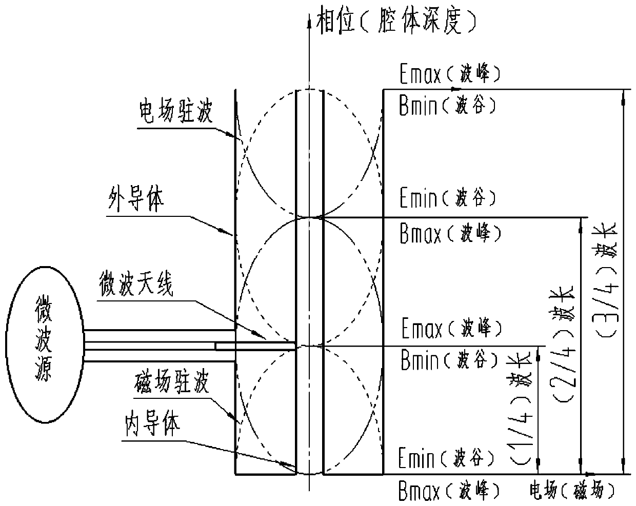
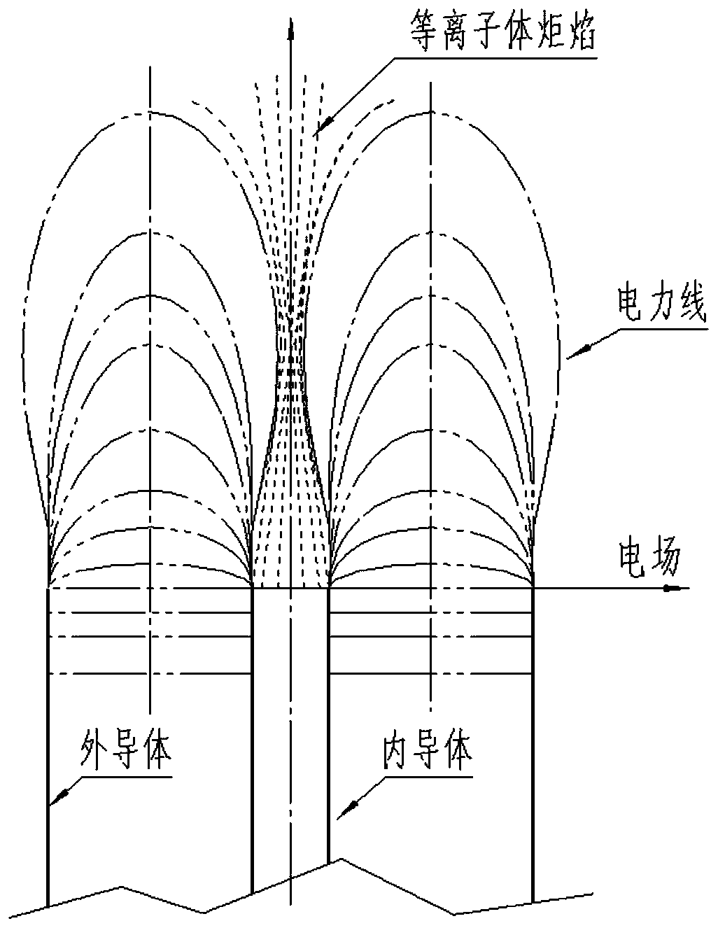
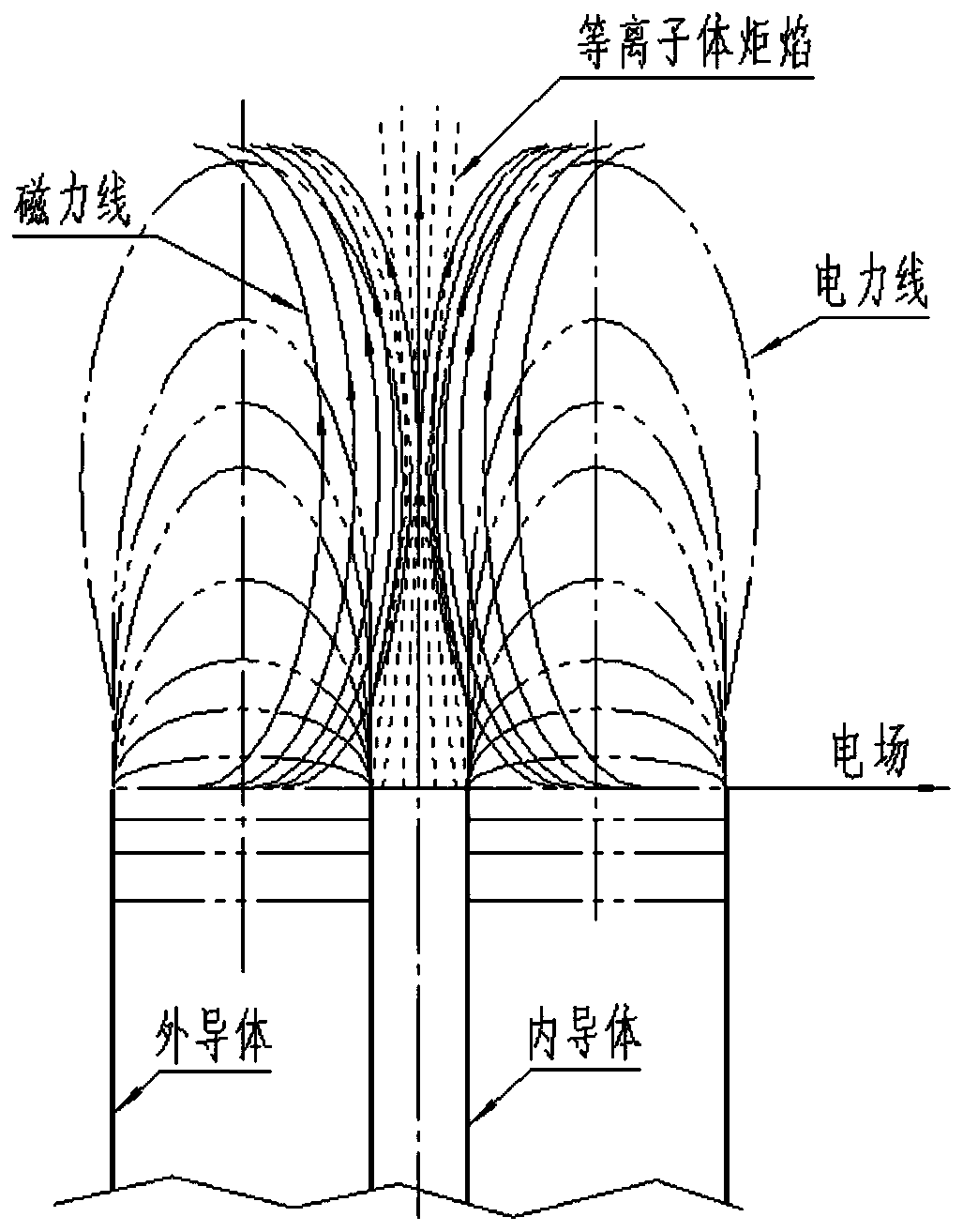
technical field [0001] The invention belongs to the technical field of microwave energy application, and at the same time belongs to the technical field of spectrochemical analysis and measurement, and in particular relates to a microwave coupled plasma generator with dual excitation functions of electromagnetic energy. Background technique [0002] The plasma obtained by microwave discharge under atmospheric pressure can be used as the excitation light source of atomic emission spectrometer, atomizer of atomic fluorescence spectrometer or ion source of mass spectrometer, and is a very important excitation source in the field of spectrochemical analysis. [0003] From the perspective of the mechanism of plasma formation, Agilent's microwave plasma (MP) belongs to the plasma obtained by simply using microwave magnetic The microwave electric field energy excites the obtained plasma. The electromagnetic field distribution of the MCP microwave resonator is as follows: figure 1...

Claims


Application Information

Patent Timeline
Patent Type & Authority Applications(China)
IPC IPC(8): H05H1/46H05H1/10
CPCH05H1/46H05H1/10
Inventor 曹彦波
Owner JILIN UNIV
Why Eureka
Eureka Blog
Learn More