Interface for Adjusting the Motion of a Powered Orthotic Device through Externally Applied Forces
- Summary
- Abstract
- Description
- Claims
- Application Information
AI Technical Summary
Benefits of technology
Problems solved by technology
Method used
Image
Examples
third embodiment
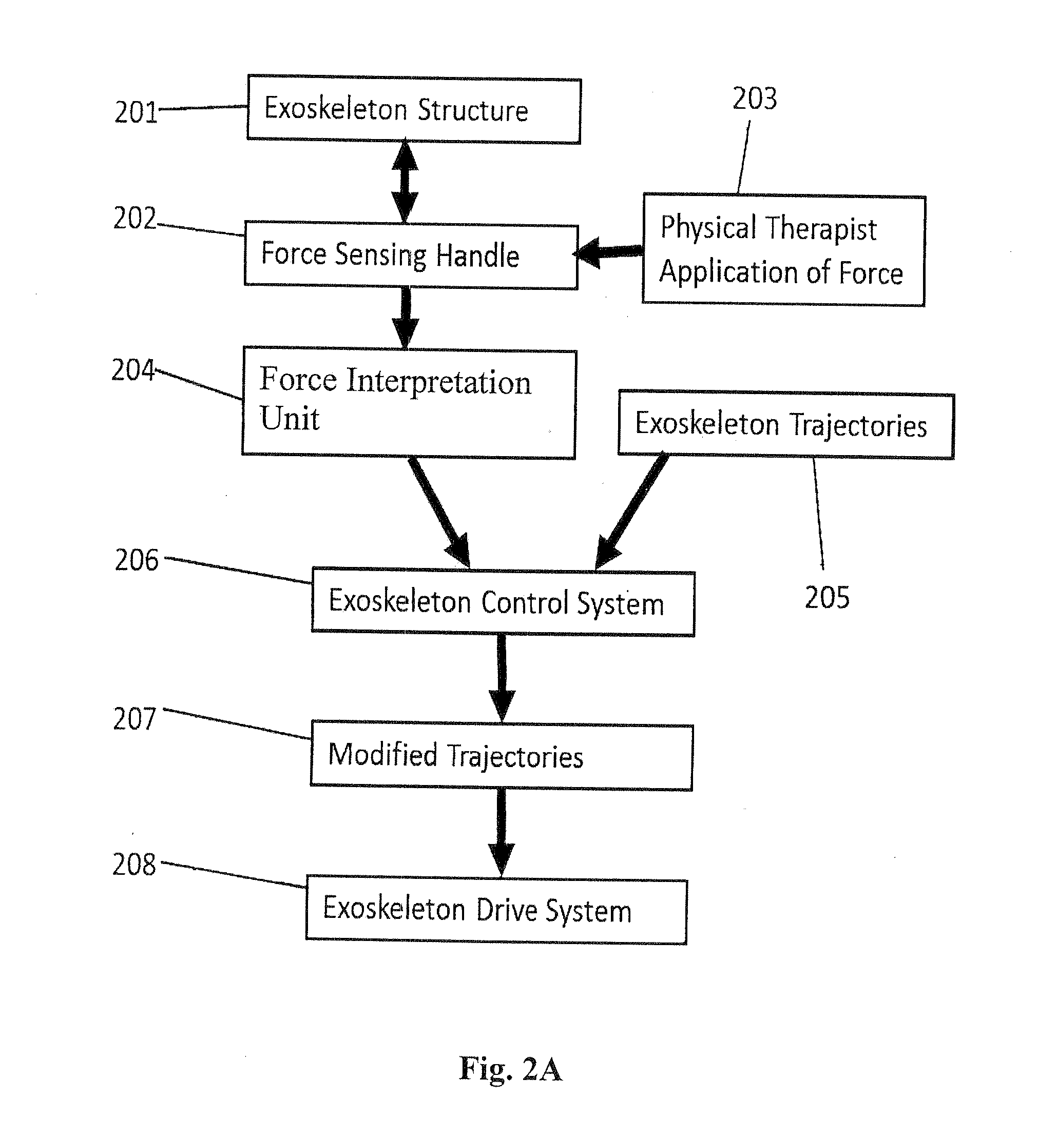
[0058]In some cases, this third embodiment might make use of a force interpretation arrangement corresponding to that shown in FIG. 2B, discussed previously, and described by equations 1 and 2, and may incorporate a method in which the force may be filtered to provide a smoother response such as that discussed previously and described by equations 3 and 4.
[0059]This third embodiment would be beneficial when making new movements not already programmed into the exoskeleton trajectories. For example, if a person wearing an exoskeleton were seated, they could grab a force sensing handle on their thigh to reposition their leg, rather than needing to awkwardly shift their entire body to throw the leg around as they would without this invention. In this example, the wearer would use their hand to lift the force sensing handle attached to the thigh of the exoskeleton, signaling the exoskeleton control system to cause portions of the exoskeleton connected to the handle and the wearer's leg t...
fourth embodiment
[0060]In a fourth embodiment, the force sensor on the force sensing handle could be no more than a switch, indicating that when the force sensing handle is grabbed the operator, who could be either the wearer of the exoskeleton or the physical therapist, wishes to move the leg of the exoskeleton. In this case, the exoskeleton would calculate the torques necessary to apply at the exoskeleton device joints to cancel the weight of the leg and the exoskeleton (a type of control commonly called “gravity compensation”) and apply the calculated torques to the joints when the operator grabs the handle. With the leg ‘weightless’, the person controlling the exoskeleton could easily maneuver the leg using forces applied to the force sensing handle, as described above, or by application of force to the exoskeleton or appendage by other means. In some embodiments, the switch need not even be in a handle, but could be any user interface, such as a switch elsewhere on the exoskeleton device, on a ...
fifth embodiment
[0063]A fifth embodiment provides an exoskeleton wearer or physical therapist with an intuitive input arrangement to modify the trajectories of future exoskeleton movements. In a representation of this embodiment, shown as a block diagram in FIG. 6A, the exoskeleton operator 601, who might be either the exoskeleton wearer or a physical therapist, first uses an input method 602 to select a pre-determined parameter that will determine the response of the exoskeleton control system 603 to subsequent commands. Exoskeleton operator 601 then exerts force on force sensing handle 604 which is mounted on the exoskeleton structure 605. Force sensing handle 604 senses this force and transmits a signal to the force interpretation unit 606, which measures the magnitude and direction of forces exerted on force sensing handle 604. Force interpretation unit 606 transmits a signal to exoskeleton control system 603. Based on both the predetermined parameter input using input method 602 and the signal...
PUM
 Abstract
Description
Claims
Application Information
 - R&D
- Intellectual Property
- Life Sciences
- Materials
- Tech Scout
- Unparalleled Data Quality
- Higher Quality Content
- 60% Fewer Hallucinations
Browse by: Latest US Patents, China's latest patents, Technical Efficacy Thesaurus, Application Domain, Technology Topic, Popular Technical Reports.
© 2025 PatSnap. All rights reserved.Legal|Privacy policy|Modern Slavery Act Transparency Statement|Sitemap|About US| Contact US: help@patsnap.com


