
Joining system

Inactive Publication Date: 2015-12-17
BW RESINS
View PDF4 Cites 0 Cited by
  • Summary
  • Abstract
  • Description
  • Claims
  • Application Information

AI Technical Summary

Benefits of technology

The patent aims to address the problems of floor patterns by providing a joining system that allows for the creation of various floor patterns and the reuse of floor boards.

Problems solved by technology

This is essential when laying indoor floors since any difference in height between the individual floor boards is unacceptable.
Further, there is no need for providing any of the floor boards with protrusions for engagement, such as e.g. a tongue, which not only makes the floor boards unnecessarily wide but also unnecessarily fragile.

Method used


Image

  • Joining system
  • Joining system

Examples


Embodiment Construction

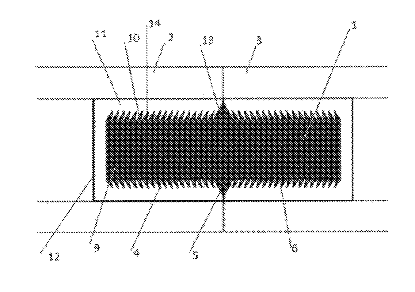
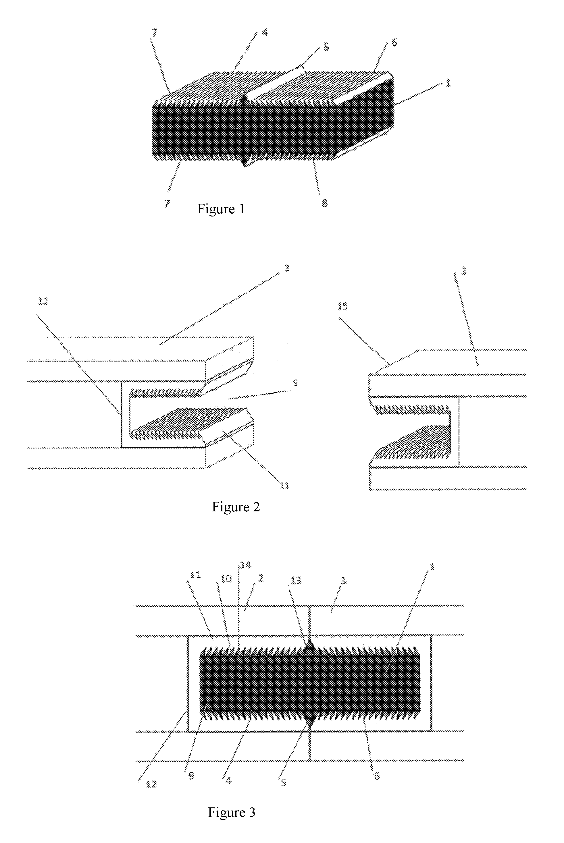
[0025]FIG. 1 shows a joining system comprising a locking device 1 and first and second elements 2, 3 to be joined by the locking device 1.

[0026]The locking device 1 has a first end section 4, a centre section 5, and a second end section 6, where the first and second end sections 4, 6 extend in opposite directions from the centre section 5. In a preferred embodiment, the locking device 1 has substantially the shape of a right parallelepiped. I.e., the locking device 1 is shaped as a right-angled block having six sides. Two first opposing sides have a mutually identical shape while the adjacent two, second opposing sides also have a mutually identical shape. The shape of the second opposing sides could be identical to that of the first opposing sides. However, it could also be different in terms of dimensions. The remaining two third opposing sides of the block can also be described as the short ends of the block. The block preferably has an elongated shape.

[0027]However, the shape of...


PUM


Abstract

The present invention relates to a joining system comprising a locking device (1) and a first element (2) and a second element (3) to be joined by the locking device (1). The locking device (1) comprises a first end section (4), a centre section (5), and a second end section (6). The first and second end sections (4, 6) extend in opposite directions from the centre section (5), and at least one surface (7) of each of the first and second end sections (4, 6) are provided with at least one barb (8). The barb (8) is angled in a direction towards the centre section (5). The first and second elements (2, 3) are each provided with a groove (9). The locking device (1) is completely enclosed by the grooves (9) when the first and second elements (2, 3) are joined by the locking device (1).

Description

FIELD OF THE INVENTION[0001]The present invention relates to a joining system comprising a locking device and a first element and a second element to be joined by the locking device. The locking device comprises a first end section, a centre section, and a second end section. The first and second end sections extend in opposite directions from the centre section. At least one surface of each of the first and second end sections are provided with at least one barb, angled in a direction towards the centre section.BACKGROUND OF THE INVENTION[0002]It is well known in the art to join elements such as floor boards to each other when laying a floor. One common solution is to design the sides of the floor boards such that one short side and one long side of each floor board is provided with a groove and one short side and one long side of each floor board is provided with a corresponding tongue. When mounting the floor, each tongue of a floor board is fitted into a corresponding groove of ...

Claims


Application Information

Patent Timeline
IPC IPC(8): E04F15/02
CPCE04F15/02005E04F2201/0511E04F2201/0107E04B1/615E04F15/041E04F15/02038E04F2201/044E04F2201/0505
Inventor DELLRUP, MAGNUS
Owner BW RESINS
Learn More