
Steam Generation Device and Household Electric Steam Box

Inactive Publication Date: 2013-04-11
SHENZHEN CRASTAL TECH CO LTD
View PDF16 Cites 2 Cited by
  • Summary
  • Abstract
  • Description
  • Claims
  • Application Information

AI Technical Summary

Benefits of technology

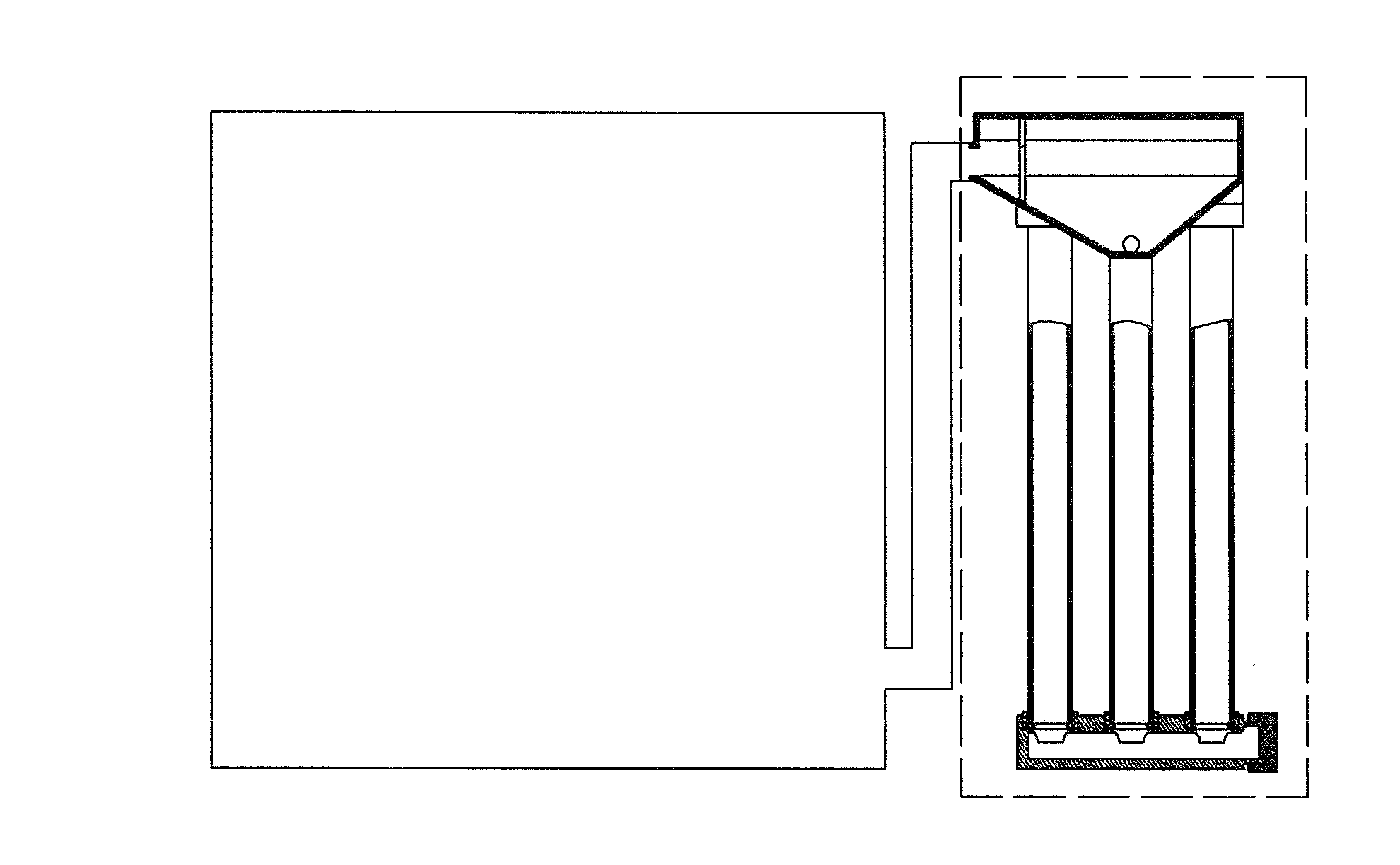
The present invention provides a steam generation device that is energy and water efficient. The device includes a water tank, a steam-water separating device, and a guiding valve. The water tank has a water returning inlet and the base assembly has a water returning tube connected to the inlet. The base assembly also has a flat bottom wall and an inclined bottom wall near the water returning tube. The steam-water separating device has an air outlet and the water tank has a water outlet connected to the guiding valve through a passage. The flat bottom wall has a connecting tube connected to the passage through a passage, and the inclined bottom wall has a connecting tube connected to the passage through another passage. The overall structure of the device can be simplified by connecting separate passages.

Problems solved by technology

1. When a water storing tank has a relatively small water outlet (that is, when the flow rate of the water flowing from the water storing tank to a water supply tube is relatively small), and when the water supply tube (corresponding to a passage IV of the present invention) has a considerable amount of air residing therein, the water outlet may have a water blocking phenomenon so that when the household steaming box is operating, the air resided in the water supply tube (corresponding to a passage IV of the present invention) may not be discharged out of the water supply tube and this leads to inadequate or lack of supply of water to the heating tube. The heating tube may overheat and this presents a potential danger to users.
2. When a valve is provided at the water outlet of the water storing tank, the water outlet is also substantially blocked. This causes a smaller amount of water to flow into the water supply tube. In this case, the heating tube may also overheat and this also presents a potential danger to users.

Method used


Image

  • Steam Generation Device and Household Electric Steam Box
  • Steam Generation Device and Household Electric Steam Box
  • Steam Generation Device and Household Electric Steam Box

Examples


embodiment 1

[0044]Referring to FIG. 9 to FIG. 10 of the drawings, the household steaming device comprises an outer casing 19, a steaming chamber 18, a steam generation device 17, wherein the steam generation device 17 is disposed in the outer casing 19. When the steam generation device 17 is operating (i.e. when a door of the steaming chamber 18 is closed), the steaming chamber 18 and the steam generation device 17 is arranged to be connected by a passage V 12 to form an enclosed structure.

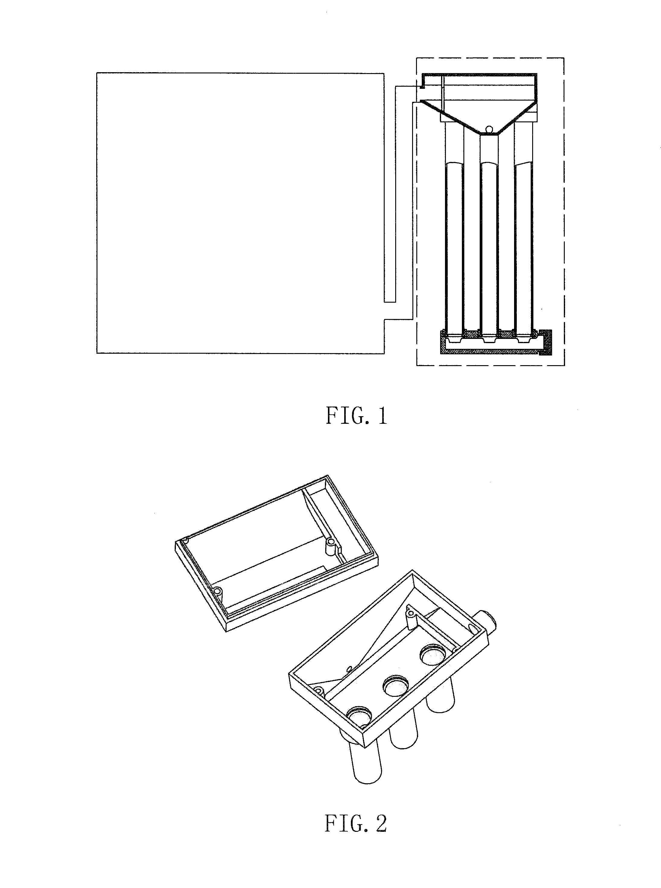
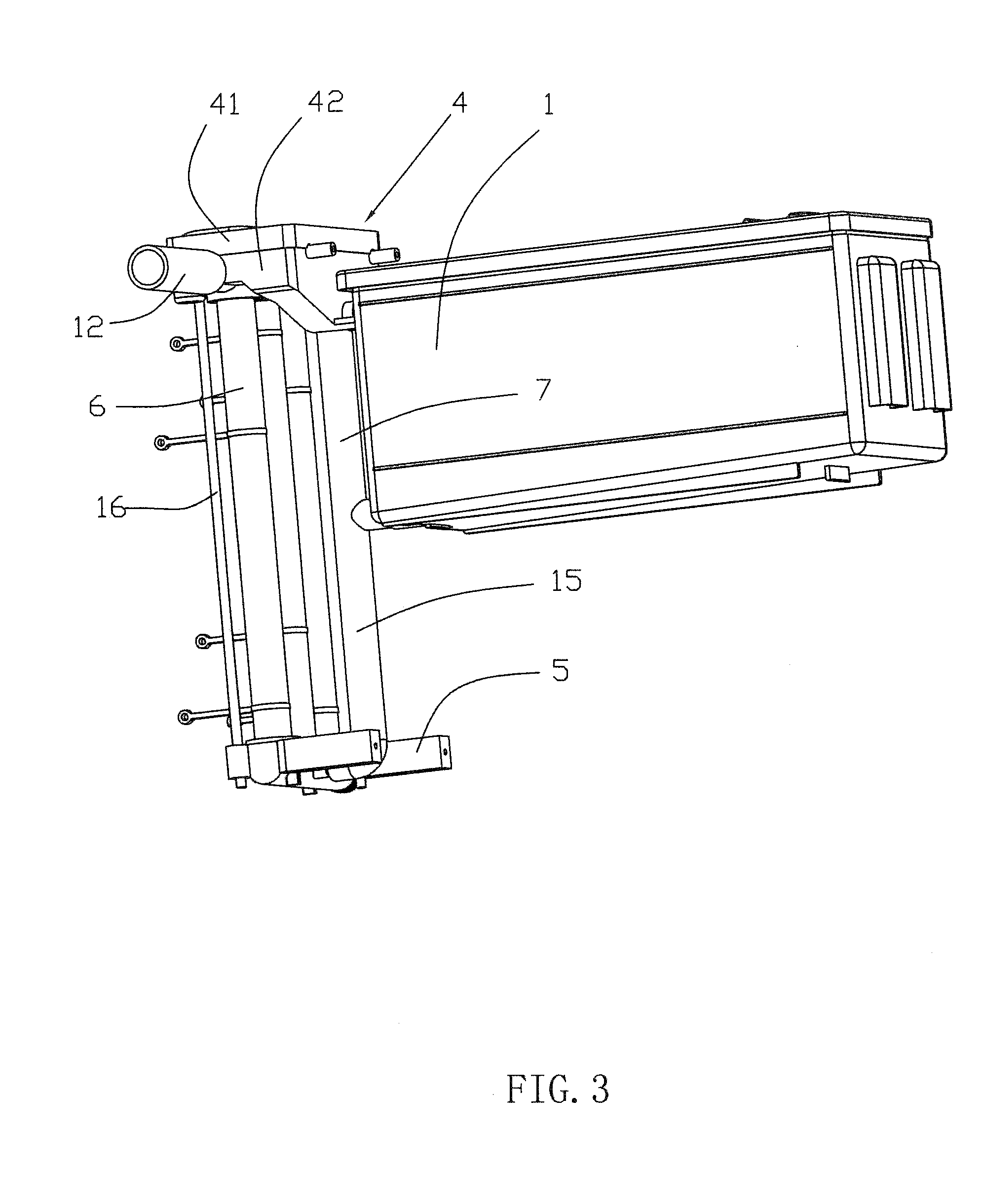
[0045]Referring to FIG. 3 of the drawings, the steam generation device 17 comprises a water tank 1, a steam-water separating device 4 comprising a sealing cover 41 and a base 42, a guiding valve 5, and a plurality of heat generating tubes 6. Referring to FIG. 4 of the drawings, the sealing cover 41 is provided on top of the base assembly 42, and defines a cover body 412. Referring to FIG. 7a of the drawings, the sealing cover 41 comprises a blocking panel I 410, and a guiding curve 411. Referring to FIG. 7b o...

embodiment 2

[0051]Referring to FIG. 5 and FIG. 7c of the drawings, the main difference between the second and the first embodiment described above is that the connecting tube 422 is provided on the inclined bottom wall 423. The connecting tube 422 is connected to passage IV 15 and passage III 14 (Note: passage IV 15 and passage III 14 may also be connected to form an integral passage). The intersection between the passage IV 15 and the passage III 14 is preferably positioned adjacent to the water outlet 9.

[0052]The difference in working principles between the first embodiment and the second embodiment is that when the heat generating tube 6 has heated up the water flowing therein, a predetermined amount of steam is generated. The steam is then arranged to flow in to the corresponding connecting base 424, the right cover chamber 4122 and then to the left cover chamber 4121. The steam is then arranged to flow into the air outlet 426 and enters the steaming chamber 18 through passage V 12. On the ...

embodiment 3

[0054]Referring to FIG. 6 and FIG. 7d of the drawings, the third preferred embodiment is similar to the first embodiment and the second embodiment described above, but the main difference between the third embodiment and the first / second embodiment described above is that the connecting tube 422 is absent in the base assembly 42. Passage V 12 is connected to a passage II 13 (Note: passage II 13 and passage V 12 may also be connected to form an integral passage), which is connected to passage IV 15 (Note: passage II 13 and passage IV 15 may also be connected to form an integral passage). Passage II 13 may be positioned anywhere with respect to passage V 12, but it should be positioned near the steaming chamber 18.

[0055]The working principles of the third embodiment is similar to the first embodiment and the second embodiment, the main difference being when the heat generating tube 6 has heated up the water flowing therein, a predetermined amount of steam is generated. The steam is th...


PUM


Abstract

A steam generation device includes a water tank, a steam-water separating device including a sealing cover and a base assembly, a guiding valve, at least one heat generating tube, wherein said water tank has a water returning inlet while said base assembly has a water returning tube connected to said water returning inlet, wherein said base assembly has a flat bottom wall and an inclined bottom wall formed at a bottom side of said base assembly at a position near said water returning tube, wherein said steam-water separating device has an air outlet, wherein said water tank further has a water outlet connected to said guiding valve through passage IV, wherein said steam-water separating device and said passage IV are connected with each other. The present invention also provides a household steaming device which is safe, energy efficient and water efficient.

Description

BACKGROUND OF THE PRESENT INVENTION[0001]1. Field of Invention[0002]The present invention relates to a steam generation device and a household electrical steaming box.[0003]2. Description of Related Arts[0004]There exist many household electrical steaming devices as conventional technology. For example, the inventor of the present invention applied for a Chinese patent having a filing date of Feb. 12, 2010 and an application number of 201010114441.6 [the title of that patent application is household steaming box]. This patent application discloses a household steaming box which is highly efficient in steaming, and extremely simple in assembling. However, the household steaming box also possesses a number of disadvantages:[0005]1. When a water storing tank has a relatively small water outlet (that is, when the flow rate of the water flowing from the water storing tank to a water supply tube is relatively small), and when the water supply tube (corresponding to a passage IV of the pre...

Claims


Application Information

Patent Timeline
IPC IPC(8): F16T1/00
CPCF22B1/284F16T1/00F24C15/327
Inventor ZHANG, BEIWANG, TIANLIANGHANG, FAXIFENG, CAIHE
Owner SHENZHEN CRASTAL TECH CO LTD
Learn More