Supercharge Your Innovation With Domain-Expert AI Agents!

Hydraulic Fracturing Isolation Methods and Well Casing Plugs for Re-fracturing Horizontal Multizone Wellbores

a technology of hydraulic fracturing and well casing, which is applied in the direction of fluid removal, wellbore/well accessories, sealing/packing, etc., can solve the problems of insufficient production, insufficient production, and inability to meet the requirements of production zones. to achieve the desired level of production, and incur too much expens

Active Publication Date: 2016-01-07
BAKER HUGHES INC
View PDF8 Cites 10 Cited by
  • Summary
  • Abstract
  • Description
  • Claims
  • Application Information

AI Technical Summary

Benefits of technology

The present disclosure is directed to a method and system for refracturing a horizontal wellbore using plugs made of proppant and polymer. The method and system allow for the selective isolation of a portion of the wellbore for hydraulic fracturing, while providing better results and minimizing damage to the wellbore. The plugs are designed to be easily pumped and positioned in the wellbore, and the system includes a packing element to seal the annulus between the tubing string and the casing. The technical effects of the method and system include improved wellbore control, reduced damage to the wellbore, and improved wellbore production.

Problems solved by technology

A production zone within a wellbore may have been previously fractured, but the prior hydraulic fracturing treatment may not have adequately stimulated the formation leading to insufficient production results.
Even if the formation was adequately fractured, the production zone may no longer be producing at desired levels.
Of concern is the problem faced due to the multiple open fractures that already exist within the horizontal wellbore from previous hydraulic fracturing stimulation treatments.
The use of expandable tubulars or cladding may not adequately provide the desired results and further, may incur too much expense in the effort to increase production from the wellbore.

Method used


Image

  • Hydraulic Fracturing Isolation Methods and Well Casing Plugs for Re-fracturing Horizontal Multizone Wellbores
  • Hydraulic Fracturing Isolation Methods and Well Casing Plugs for Re-fracturing Horizontal Multizone Wellbores
  • Hydraulic Fracturing Isolation Methods and Well Casing Plugs for Re-fracturing Horizontal Multizone Wellbores

Examples


Embodiment Construction

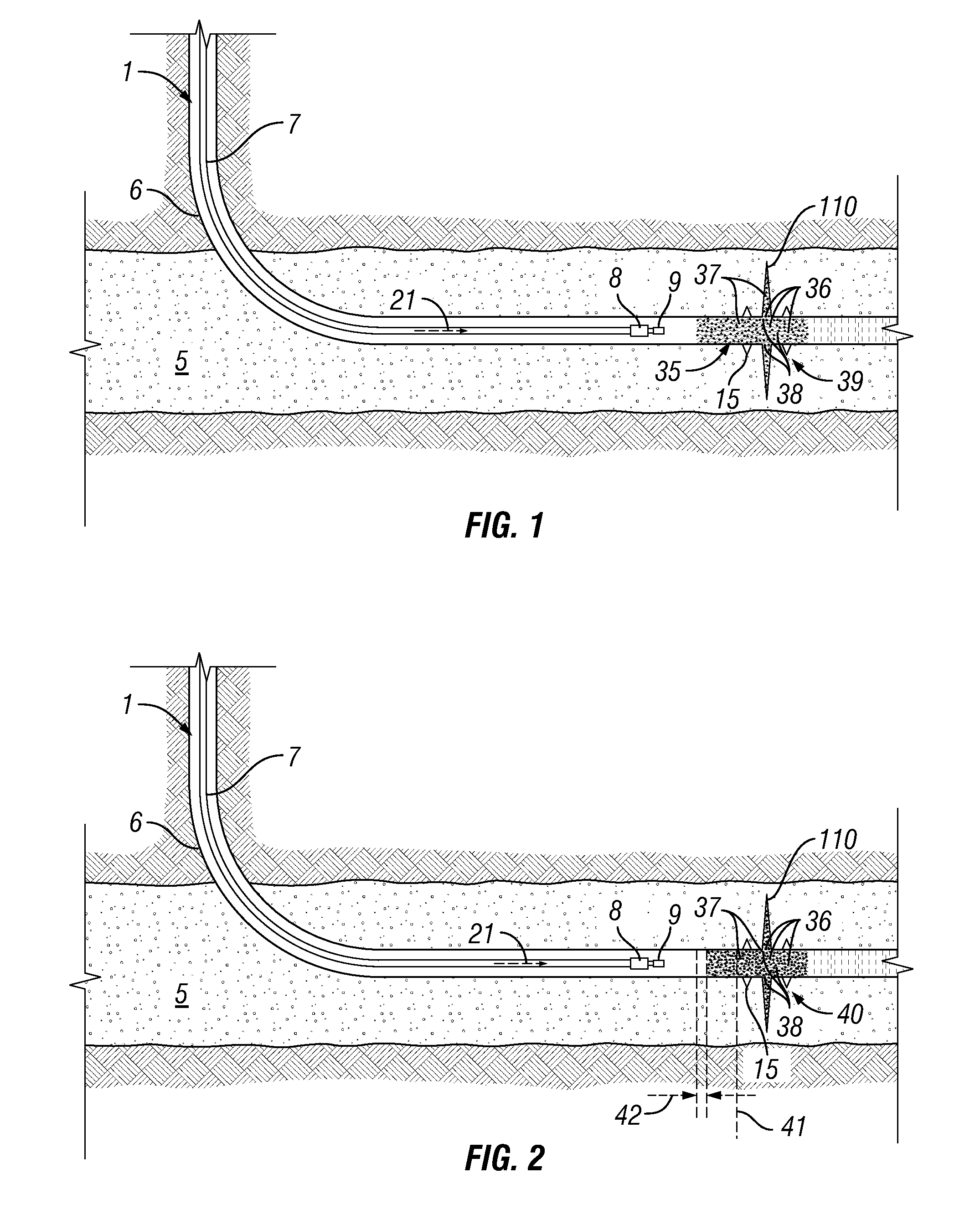
[0027]FIG. 1 shows coiled tubing string 7 positioned within the casing 6 of a wellbore 1. The coiled tubing 6 is used to position a fluid pill comprised of proppant 36, lightweight filler 38, and polymer 37 at a location adjacent and / or proximate to a previously fractured location that has been re-fractured 110. A fluid pill 35 comprising proppant 36, lightweight filler 38, and polymer 37 is used to selectively hydraulically isolate the re-fractured location 110, as detailed herein. After the placement of the fluid pill 35 of proppant 36, lightweight filler 38, and polymer 37, fluid is slowly pumped down the coiled tubing 7 as indicated by arrow 21. The pumped fluid causes the pill 35 to start to bridge off 39 as shown in FIG. 1. The bridging off pill 39 may hydraulically isolate the re-fractured location 110 as well as perforations 15 in the casing 6 that may be adjacent to the re-fractured location 110. FIG. 2 shows the pill 35 bridged off to form a plug 40 that hydraulically isol...


PUM


Abstract

A method for hydraulically isolating a portion of a multizone wellbore by providing a plug proximate the portion of the wellbore. The plug may be a proppant combined with a polymer. The proppant may be an ultra-lightweight proppant and the polymer may be cross-linked. The polymer may be a superabsorbent polymer or a hydrophobically modified polysaccharide. The plug may be formed by placing a pill of proppant and polymer within the wellbore and slowing pumping fluid down to cause the pill to bridge off and form a plug. The pill may also include a lightweight filler. The plug may be used to hydraulically isolate a portion of the wellbore during a fracturing or re-fracturing process. Multiple plugs may be placed along the wellbore to hydraulically isolate portions of the wellbore during the fracturing or re-fracturing process.

Description

FIELD OF THE DISCLOSURE [0001]The embodiments described herein relate to a method and system to enable the re-stimulation through means of hydraulic fracturing of horizontal multizone wellbores. The method and system uses wellbore plugs that may be comprised of various combinations of proppants, and ultra-lightweight proppants, and lightweight fillers, and polymers. The plugs may be used to hydraulically isolate portions of a wellbore during the re-fracturing treatment process.BACKGROUNDDescription of the Related Art[0002]Natural resources such as gas and oil may be recovered from subterranean formations using well-known techniques. For example, a horizontal wellbore may be drilled within the subterranean formation. After formation of the horizontal wellbore, a string of pipe, e.g., casing, may be run or cemented into the wellbore. Hydrocarbons may then be produced from the horizontal wellbore.[0003]In an attempt to increase the production of hydrocarbons from the wellbore, the casi...

Claims


Application Information

Patent Timeline
Patent Type & Authority Applications(United States)
IPC IPC(8): E21B43/267E21B33/124E21B43/14
CPCE21B43/267E21B33/124E21B43/14E21B33/134
Inventor NELSON, SCOTT, G.
Owner BAKER HUGHES INC
Features
  • R&D
  • Intellectual Property
  • Life Sciences
  • Materials
  • Tech Scout
  • Unparalleled Data Quality
  • Higher Quality Content
  • 60% Fewer Hallucinations
Learn More