Vacuum wall crawler

Active Publication Date: 2016-02-11
FORCE TECH
View PDF2 Cites 8 Cited by
  • Summary
  • Abstract
  • Description
  • Claims
  • Application Information

AI Technical Summary

Benefits of technology

[0012]In a further embodiment the suction holes are so small that they will delay the reduction of vac

Problems solved by technology

These surfaces can be inconvenient, difficult or even dangerous, for people to access directly.
The difficulty can be increased when these surfaces are curved, compound, or ta

Method used


Image

  • Vacuum wall crawler
  • Vacuum wall crawler
  • Vacuum wall crawler

Examples


Embodiment Construction

[0061]In the following detailed description a vacuum wall crawler 1 and a suction track unit 100 according to the invention will be described by the preferred embodiments.

[0062]The construction and operation of a vacuum wall crawler 1 is as such well-known and should not require further explanation in the present context. However, further details regarding the operation of the vacuum wall crawler 1 are provided below.

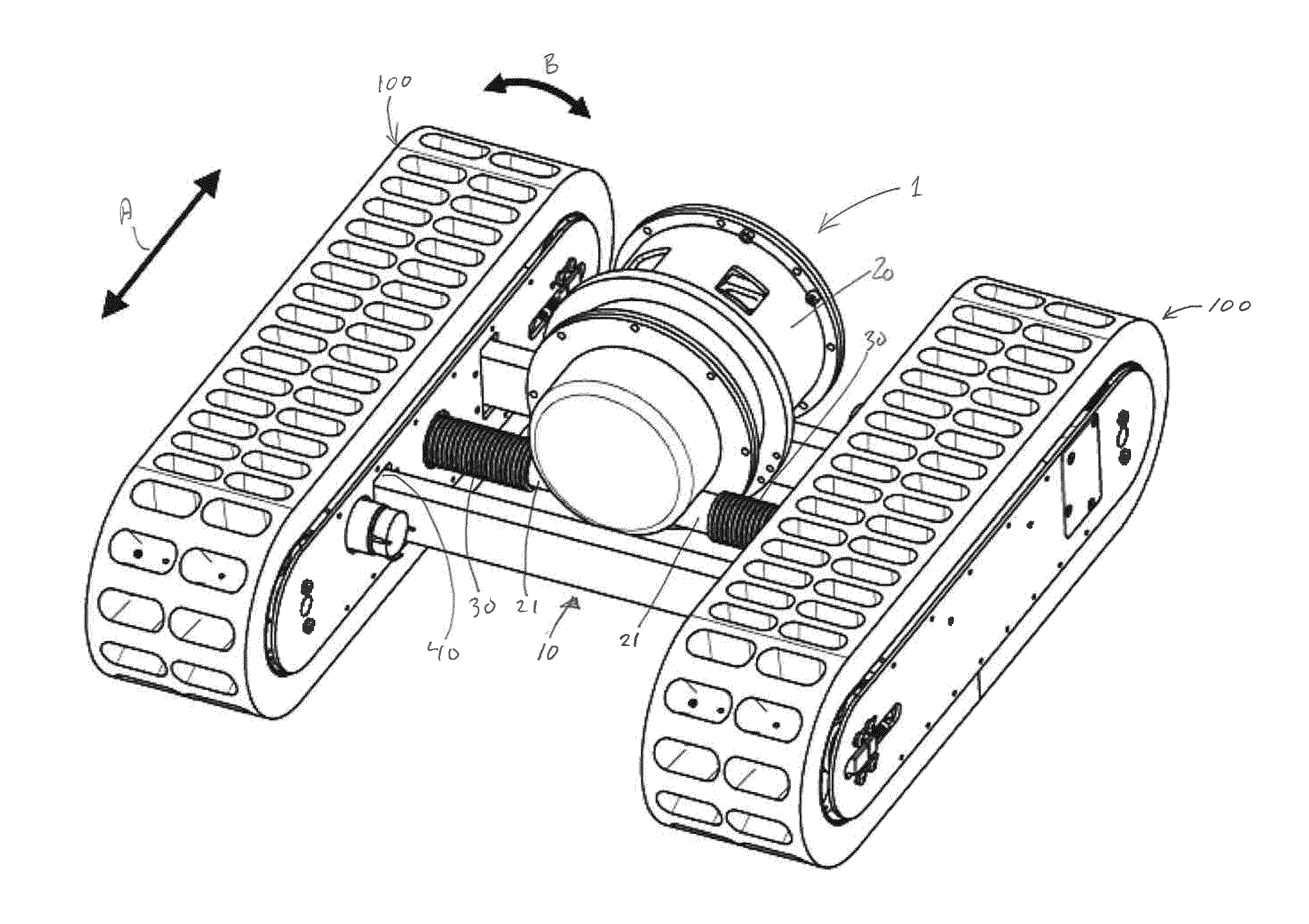
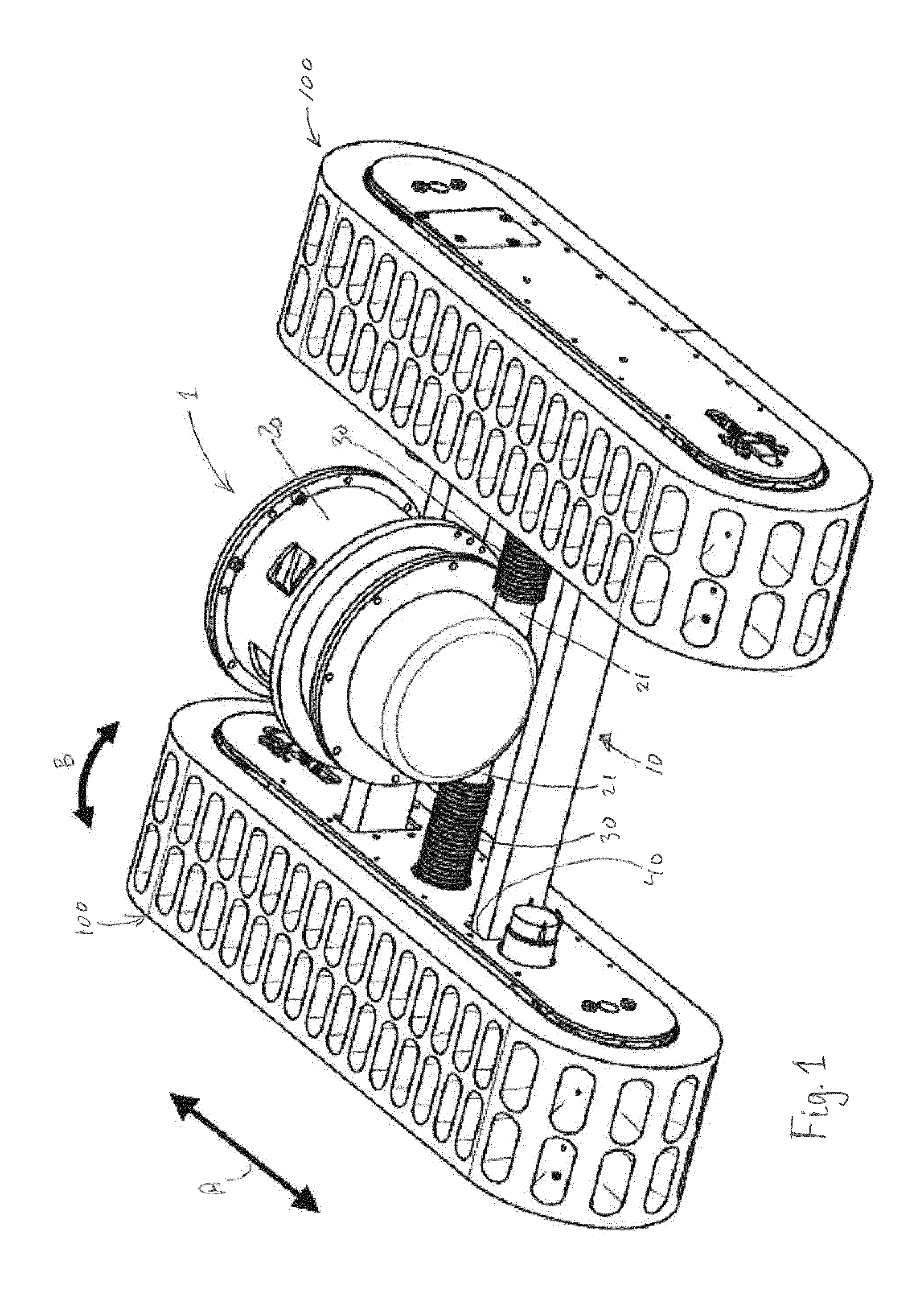
[0063]FIG. 1 shows a first exemplary embodiment of a vacuum wall crawler 1.

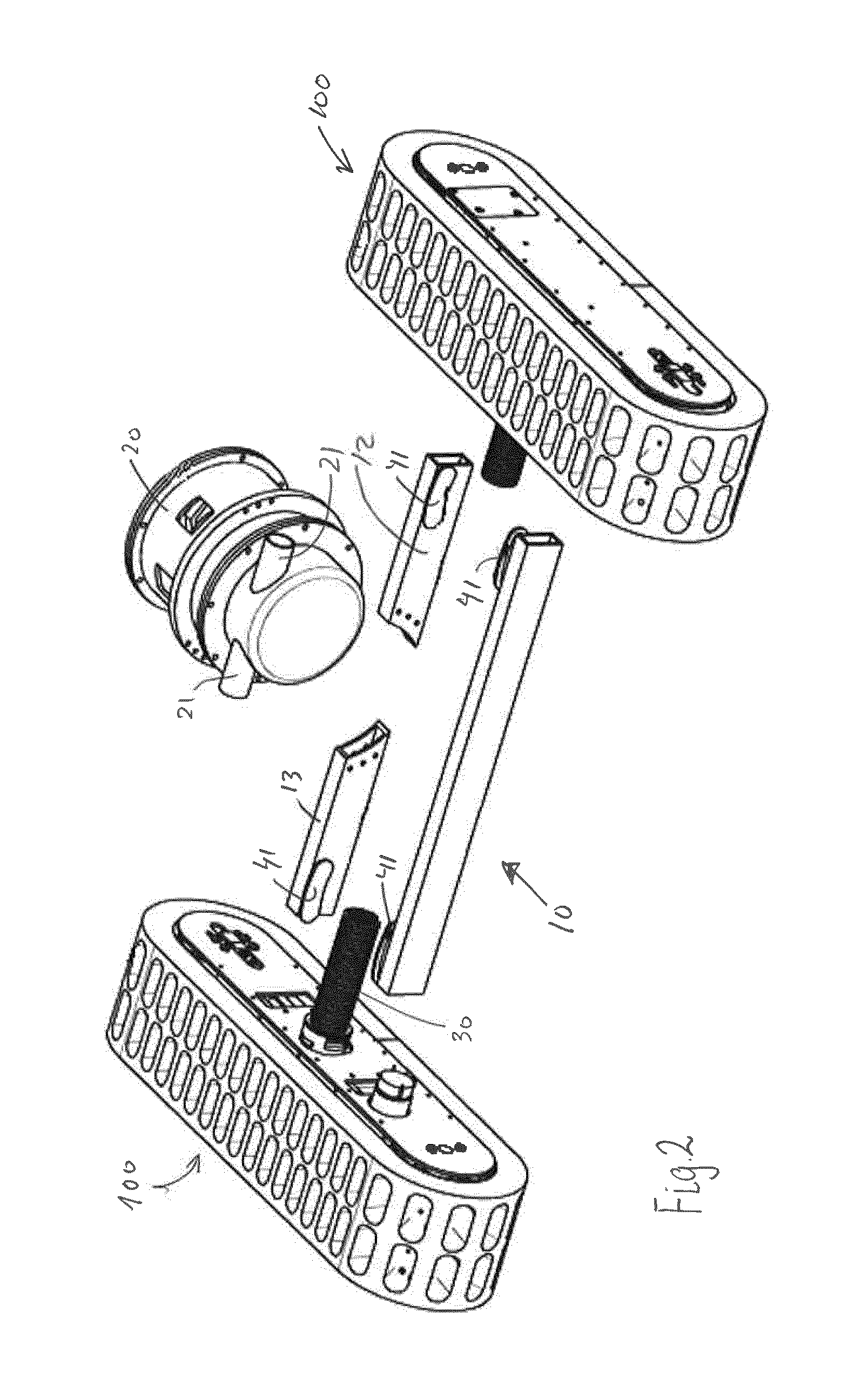
[0064]A vacuum wall crawler 1 is a moving device that is capable of attaching to a surface, such as wall or a ceiling etc. by use of one or more suction track units 100. The vacuum wall crawler 1 shown in FIG. 1 has two suction track units 100. The suction track units 100 are connected to a main frame 10 through joints 40 allowing the vacuum wall crawler 1 to adapt to curved surfaces, on which it drives, see below.

[0065]In other embodiments (not shown) a vacuum wall crawler 1 may have more than t...


PUM


Abstract

The present invention relates to a vacuum wall crawler having at least one vacuum track unit comprising a track frame, two pulleys provided in opposite ends of the track frame, and defining a wheelbase, an endless track arranged to circulate on the two pulleys, and comprising a flexible band, said flexible band comprising a plurality of apertures, and having a thickness, a vacuum distribution box provided in said track frame wherein the vacuum distribution box is in communication with a portion of the apertures to distribute a vacuum to the portion of apertures as the endless track circulates, where the thickness of the flexible band is 5-20% of the wheel base.

Description

[0001]The present invention relates to vacuum wall crawler comprising at least one suction track unit of the type having and endless track comprising a continuous band formed in a flexible material, and with a plurality apertures in the continuous band for providing a vacuum between a portion of the apertures and a surface on which the vacuum wall crawler is located or moves.BACKGROUND OF THE INVENTION[0002]For the purpose of various tasks—e.g. inspection, cleaning de-rusting, decontamination of radioactivity and repairs—in hard to access locations, such as high walls, ceilings, chimneys, the inside of pipes or tanks and other closed spaces, ships or airplane surfaces, etc., it is known in the art to utilize automatic working devices that may be operated by remote control to avoid human presence at the often dangerous location. Examples of such automatic working devices are vacuum wall crawlers, that may bring a tool or camera or the like in close proximity to a vertical, inverted, ...

Claims


Application Information

Patent Timeline
IPC IPC(8): B62D55/265B62D55/075
CPCB62D55/075B62D55/265
Inventor NIELSEN, STEEN ARNFREDHANSEN, PEDER BENT
Owner FORCE TECH
Why Eureka
Try Eureka