
Bone Distraction Device Having a Quick Release Disengagement Mechanism

a distraction device and disengagement mechanism technology, applied in the field of medical distraction devices, to achieve the effect of lengthening the maxilla or the mandibl

Inactive Publication Date: 2016-03-03
STAEHLER HEINZ +1
View PDF8 Cites 5 Cited by
  • Summary
  • Abstract
  • Description
  • Claims
  • Application Information

AI Technical Summary

Benefits of technology

[0008]The invention is a bone distractor, and is especially drawn to a bone distractor used in mandibular and maxillary craniofacial repair, reconstruction and treatment that enables a surgeon to lengthen the maxilla or the mandible. In a representative illustration, osteotomies are provided on the left and right sides of the mandible or the maxilla (or both), such that the anterior portion of the mandible or the maxilla is divided from the posterior portion. This allows the anterior portions to be repositioned in a more desirable orientation.
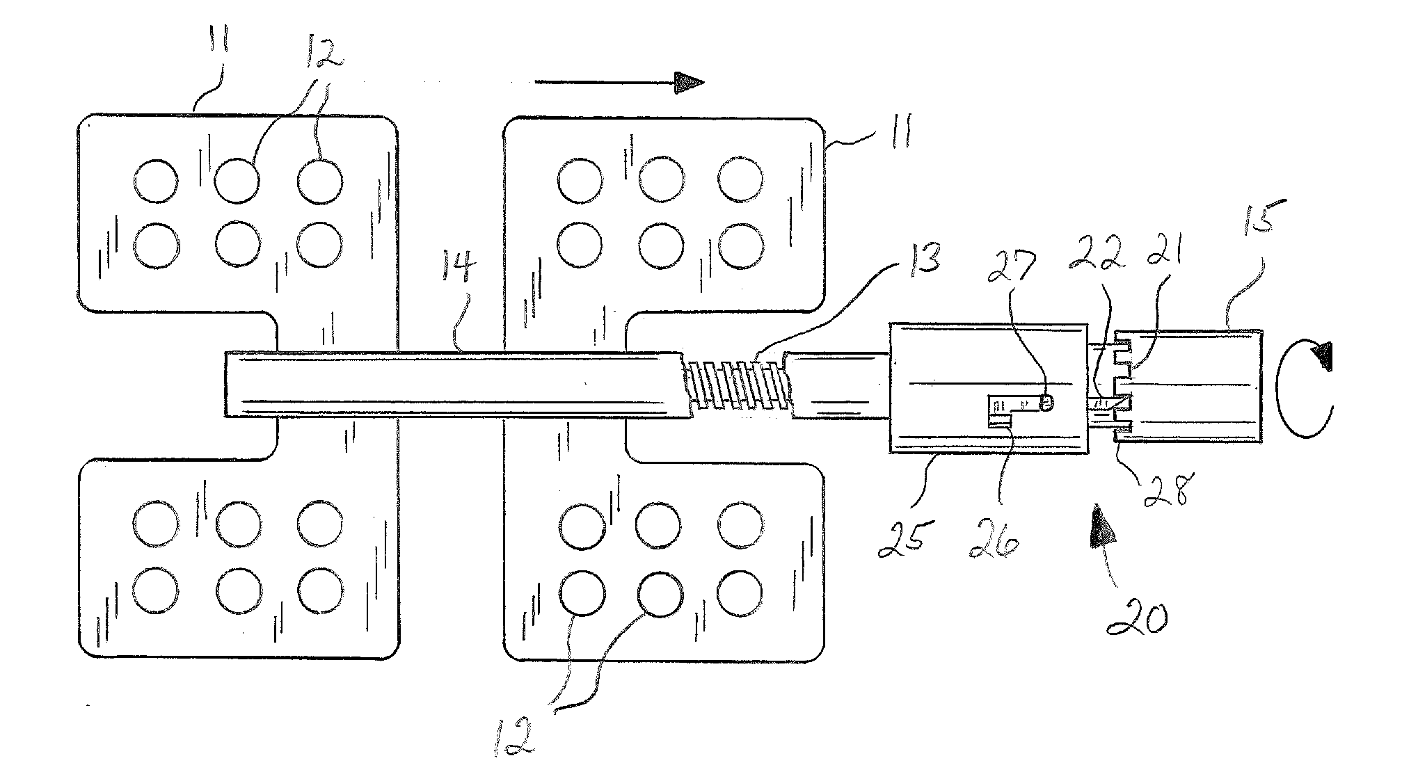
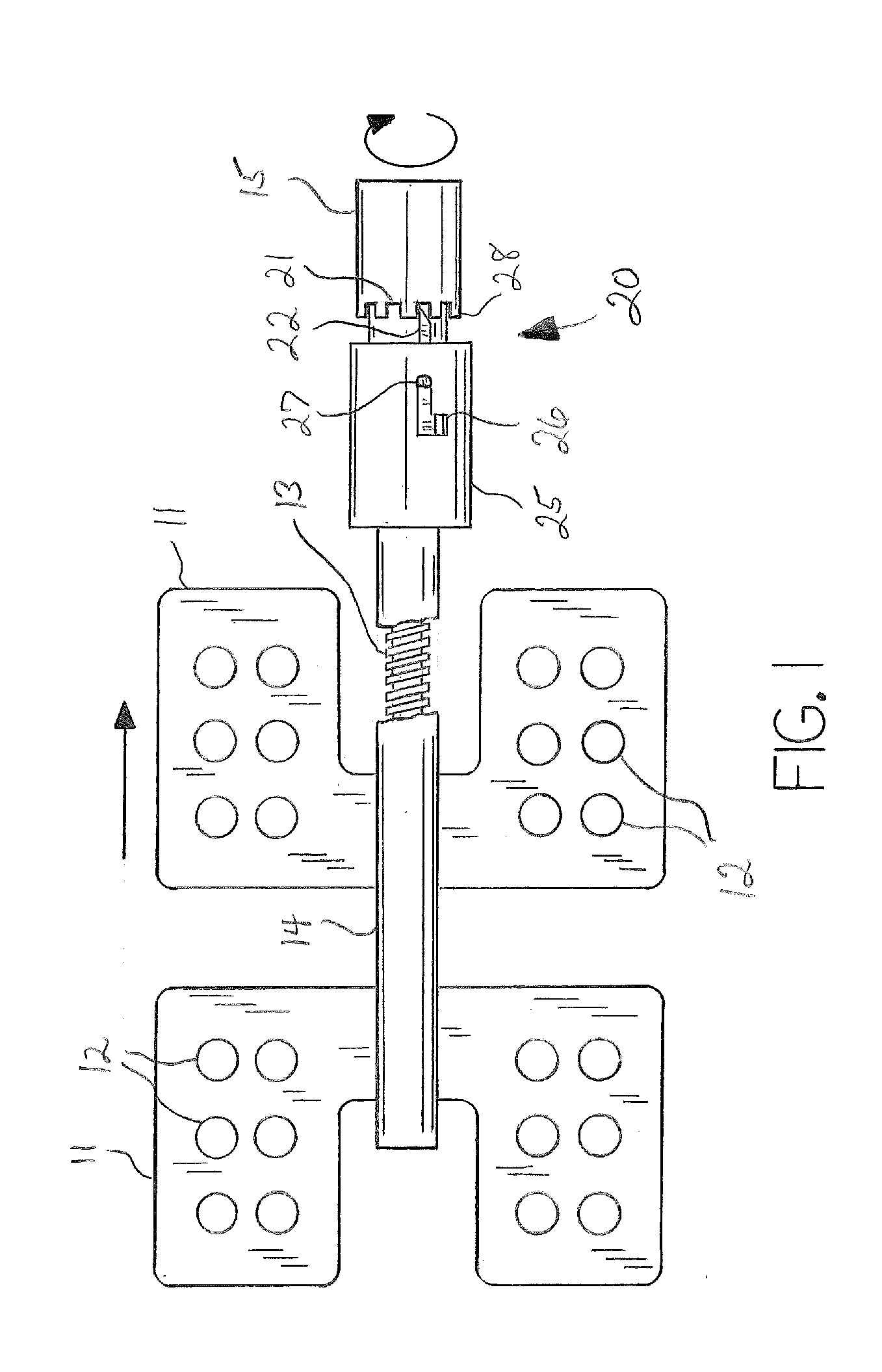
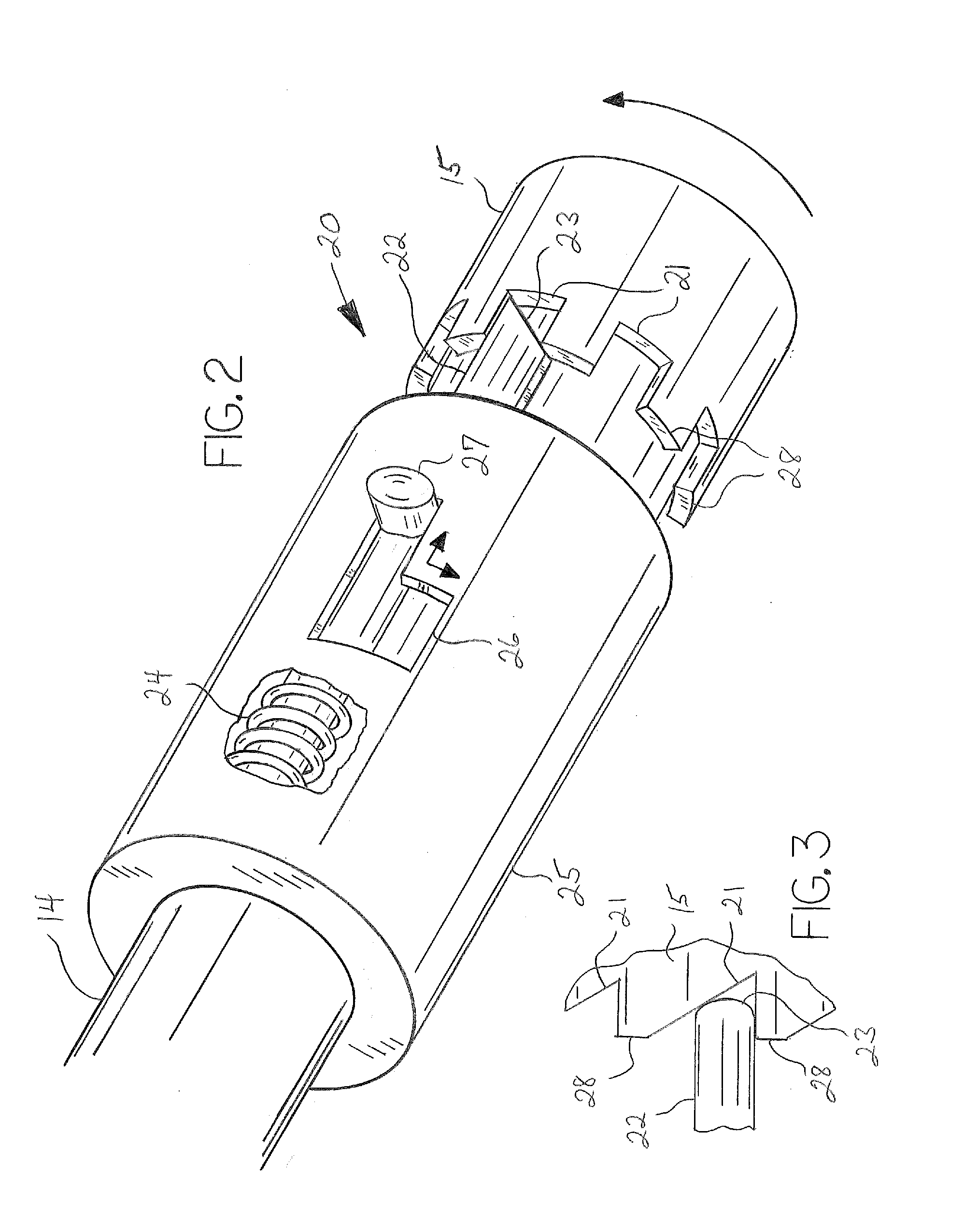
[0009]The bone distractor of the invention comprises structures for attachment of the device to a bone on opposite sides of an osteotomy gap, such as by a pair of bone plate members affixed by bone screws or similar bone attachment fasteners known in the art. The bone distractor further comprises a distraction mechanism to separate the bone plates, such that the bone portions to which the device is attached are gradually separated as well, such as by a threaded rod retained within a framework or housing, with the bone plate members mounted on one or two translatable mounting members in mechanical communication with the threaded rod, such that rotation of the threaded rod results in relative movement of one or both mounting members such that the bone plates move apart. The bone distractor device further comprises a ratchet and pawl mechanism whereby rotation of the threaded rod is allowed in only one direction while the pawl is engaged, the pawl serving to secure the threaded rod in incremental positions relative to the framework or housing, and further comprising a disengagement mechanism whereby the pawl can be quickly and easily released such that free rotation of the threaded rod in either direction is possible.

Problems solved by technology

One problem with such unidirectional distraction devices is that it may be desirable or required to contract the bone plates by rotating the threaded drive rod in the direction opposite to the distraction direction.

Method used


Image

  • Bone Distraction Device Having a Quick Release Disengagement Mechanism
  • Bone Distraction Device Having a Quick Release Disengagement Mechanism
  • Bone Distraction Device Having a Quick Release Disengagement Mechanism

Examples


Embodiment Construction

[0016]With reference to the drawings, the invention will now be described in detail with regard for the best mode and the preferred embodiment.

[0017]The invention is a bone distractor, and is especially drawn to a linear bone distractor used in mandibular and maxillary craniofacial repair, reconstruction and treatment. In a representative procedure, osteotomies are provided on the left and right sides of the mandible or the maxilla, such that the anterior portion of the bone is divided from the posterior portion of the bone. A pair of distractor devices are utilized, one for each side of the mandible or maxilla. The distractor device is affixed to the mandible or maxilla spanning the osteotomy gap. Distraction is accomplished slowly to allow bone regeneration to occur across the osteotomy gap. When the bones are properly lengthened, the device is removed.

[0018]FIG. 1 illustrates a representative embodiment of the distraction device comprising a distraction mechanism for separating a...


PUM


Abstract

A bone distraction device having a ratchet and pawl mechanism such that incremental rotation is allowed in one direction and prevented in the other, and further having a quick release mechanism such that the ratchet and pawl mechanism can be released to allow free rotation in both directions.

Description

[0001]This application claims the benefit of U.S. Non-Provisional patent application Ser. No. 12 / 284,679, filed Sep. 24, 2008, the disclosure of which is incorporated herein by reference.BACKGROUND OF THE INVENTION[0002]This invention relates generally to the field of medical distraction devices in the field of bone fixation, repair and regeneration, and more particularly relates to such devices and methods utilized in mandibular and maxillary craniofacial repair, facial reconstruction, and treatment for congenital, developmental and traumatic, defects.[0003]It is often desirable or necessary to effect reconstruction or repair of the craniofacial bones defining the face of a person, such as the midface, the mandible and / or the maxilla. This need may arise from congenital conditions, developmental disorders or trauma. In many circumstances the abnormalities are corrected by first dividing a bone through osteotomy, i.e., cutting or fracturing a bone to create two segments separated by...

Claims


Application Information

Patent Timeline
Patent Type & Authority Applications(United States)
IPC IPC(8): A61B17/80
CPCA61B17/8009A61B17/8004
Inventor STAEHLER, HEINZJOHNSTON, THOMAS
Owner STAEHLER HEINZ
Learn More