
Bone distraction device having a quick release disengagement mechanism

a disengagement mechanism and distraction device technology, applied in the field of medical distraction devices, can solve the problems of damage to the tissue, exposed edges of distraction devices, transitions having right angle junctions, etc., and achieve the effect of lengthening the maxilla or the mandibl

Active Publication Date: 2022-08-02
KLS MARTIN LP
View PDF21 Cites 0 Cited by
  • Summary
  • Abstract
  • Description
  • Claims
  • Application Information

AI Technical Summary

Benefits of technology

[0011]The invention is a bone distractor, and is especially drawn to a bone distractor used in mandibular and maxillary craniofacial repair, reconstruction and treatment that enables a surgeon to lengthen the maxilla or the mandible. In a representative use, osteotomies are provided on the left and right sides of the mandible or the maxilla (or both), such that the anterior portion of the mandible or the maxilla is divided from the posterior portion. This allows the anterior portions to be repositioned in a more desirable orientation.

Problems solved by technology

One problem with such unidirectional distraction devices is that it may be desirable or required to contract the bone plates by rotating the threaded drive rod in the direction opposite to the distraction direction.
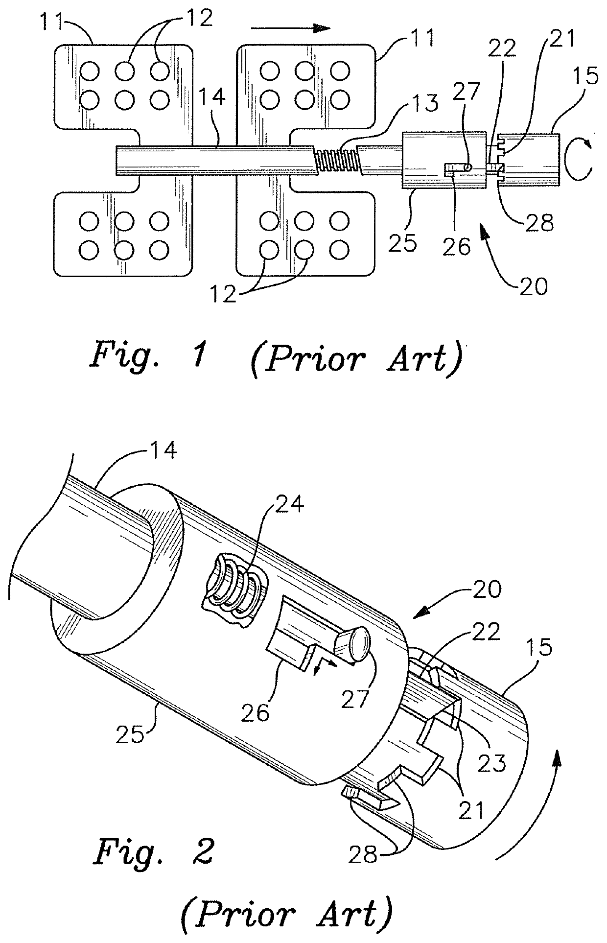
A problem inherent in the known distraction devices of the type illustrated by the Staehler reference is that the distraction devices present exposed edges and transitions having right angle junctions.
Because the devices are inserted and implanted into soft tissue, these exposed edges and transitions may result in damage to the tissue during insertion, during the distraction procedure, or during removal of the distraction device.

Method used


Image

  • Bone distraction device having a quick release disengagement mechanism
  • Bone distraction device having a quick release disengagement mechanism
  • Bone distraction device having a quick release disengagement mechanism

Examples


Embodiment Construction

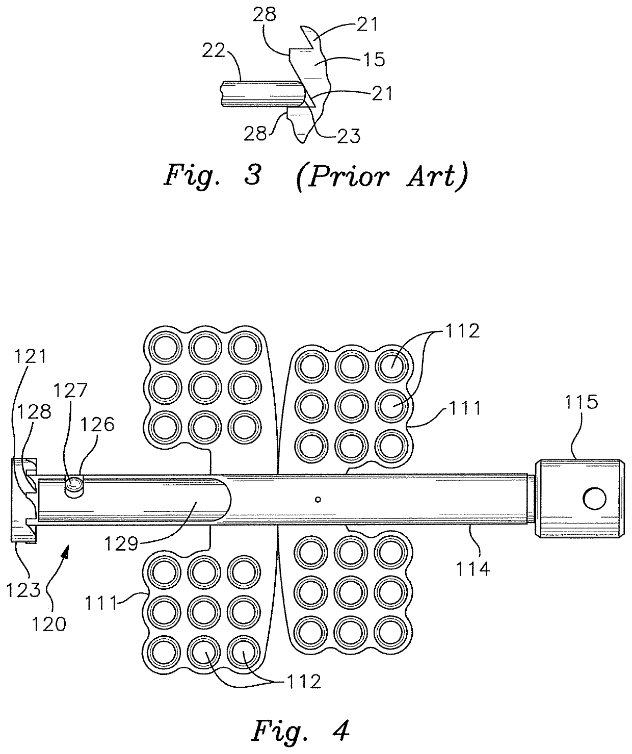
[0026]With reference to the drawings, the invention will now be described in detail with regard for the best mode and the preferred embodiments. The invention is a bone distractor, and is especially drawn to a bone distractor used in mandibular and maxillary craniofacial repair, reconstruction and treatment. In a representative procedure, osteotomies are provided on the left and right sides of the mandible or the maxilla, such that the anterior portion of the bone is divided from the posterior portion of the bone. A pair of distractor devices are utilized, one for each side of the mandible or maxilla. The distractor device is affixed to the mandible or maxilla spanning the osteotomy gap. Distraction is accomplished slowly to allow bone regeneration to occur across the osteotomy gap. When the bones are properly lengthened, the device is removed.

[0027]FIGS. 4 through 7 illustrate a representative embodiment of a first embodiment of the distraction device comprising distraction means f...


PUM


Abstract

A bone distraction device having a ratchet and pawl assembly such that incremental rotation is allowed in one direction and prevented in the other, and further having a quick release mechanism such that the ratchet and pawl mechanism can be released to allow free rotation in both directions. The device has a pawl housing mounted onto a rod housing, the pawl housing having a sloping transition shoulder diminishing to transition onto the outer surface of the rod housing. In other embodiments, the device has a sleeve housing with an enlarged end telescopically mounted onto a rod housing, the enlarged end having a sloping transition shoulder diminishing to transition onto the outer surface of the sleeve housing.

Description

BACKGROUND OF THE INVENTION[0001]This invention relates generally to the field of medical distraction devices in the field of bone fixation, repair and regeneration, and more particularly relates to such devices and methods utilized in mandibular and maxillary craniofacial repair, facial reconstruction, and treatment for congenital, developmental and traumatic defects.[0002]It is often desirable or necessary to effect reconstruction or repair of the craniofacial bones defining the face of a person, such as the midface, the mandible and / or the maxilla. This need may arise from congenital conditions, developmental disorders or trauma. In many circumstances the abnormalities are corrected by first dividing a bone through osteotomy, i.e., cutting or fracturing a bone to create two segments separated by a gap or space. In some instances the bone segments will be shifted into the proper orientation and alignment, and then fixed in place relative to each other until bone growth across the ...

Claims


Application Information

Patent Timeline
Patent Type & Authority Patents(United States)
IPC IPC(8): A61B17/66A61B17/70A61B17/64A61B17/80A61B17/68A61B17/00
CPCA61B17/663A61B17/6475A61B17/7008A61B17/8019A61B2017/00407A61B2017/681A61B17/8009A61B17/8023
Inventor STAEHLER, HEINZJOHNSTON, JR., THOMAS S.
Owner KLS MARTIN LP
Learn More