Stopwatch and timer user interfaces

a technology of user interface and timer, applied in the field of computer user interface, can solve the problems of limited functionalities and lack of intuitive methods for inputting timing values

Active Publication Date: 2016-03-03
APPLE INC
View PDF6 Cites 84 Cited by
  • Summary
  • Abstract
  • Description
  • Claims
  • Application Information

AI Technical Summary

Problems solved by technology

However, some of these functionalities may be limited in that they may display timing data in a basic manner, may not allow for user customization of timing data display parameters, and / or may not provide intuitive methods for inputting timing values by a user.

Method used


Image

  • Stopwatch and timer user interfaces
  • Stopwatch and timer user interfaces
  • Stopwatch and timer user interfaces

Examples


Embodiment Construction

[0029]The following description sets forth exemplary methods, parameters and the like. It should be recognized, however, that such description is not intended as a limitation on the scope of the present disclosure but is instead provided as a description of exemplary embodiments.

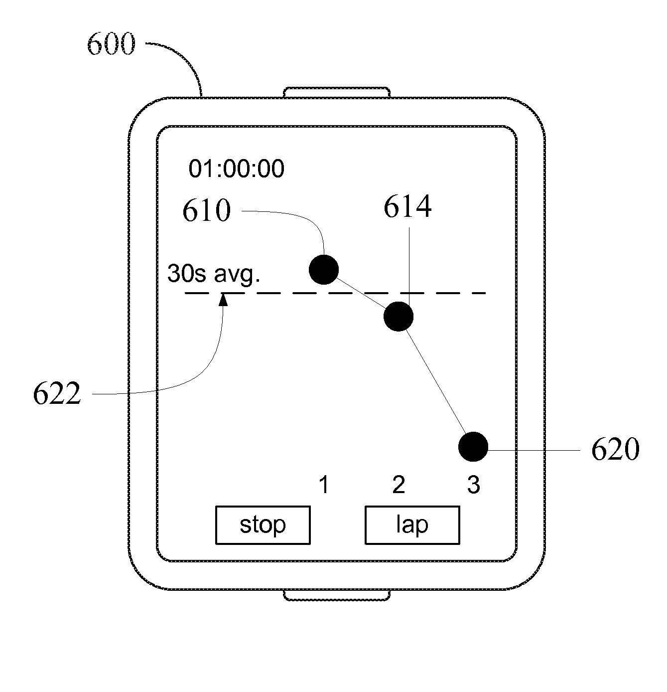
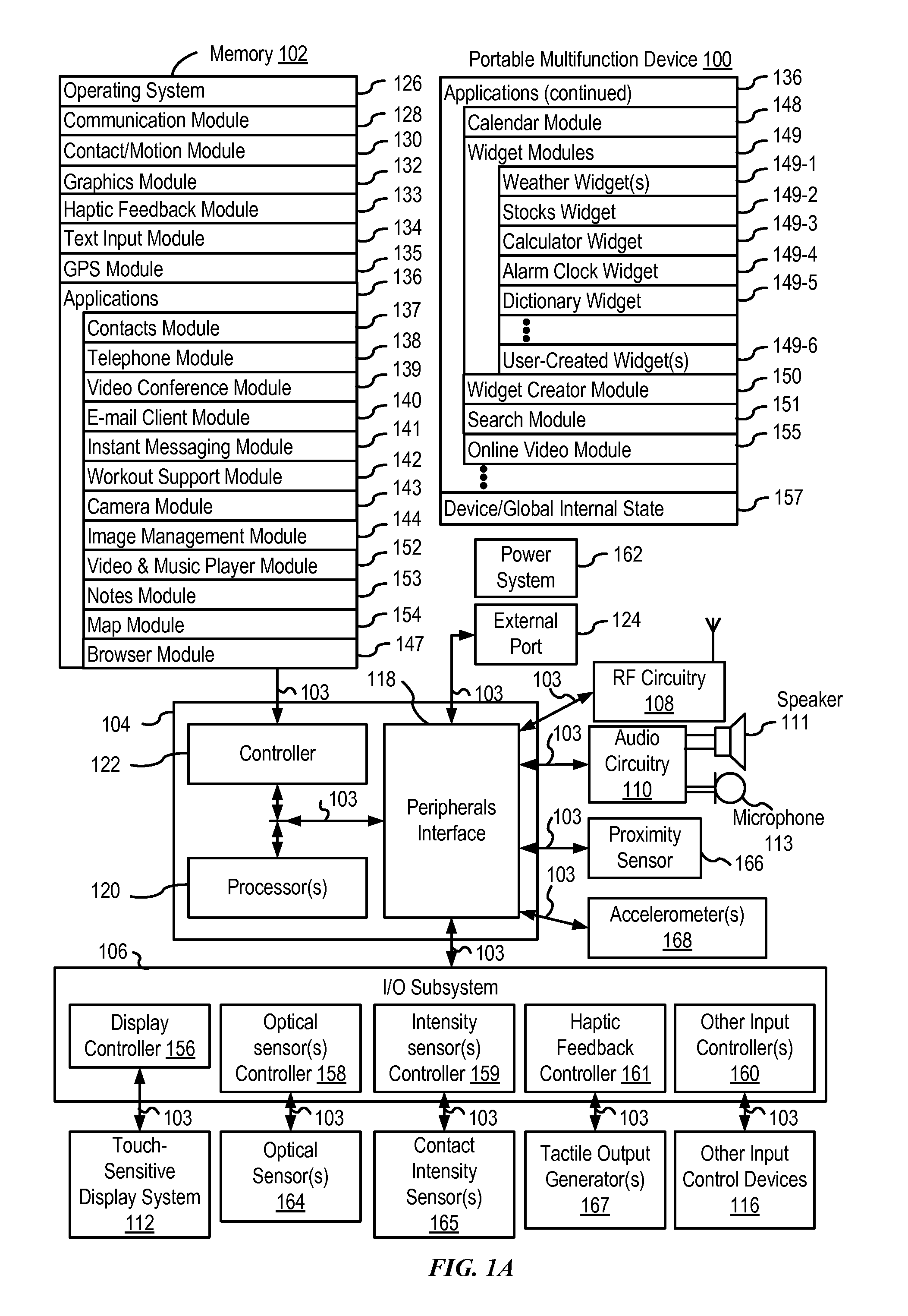
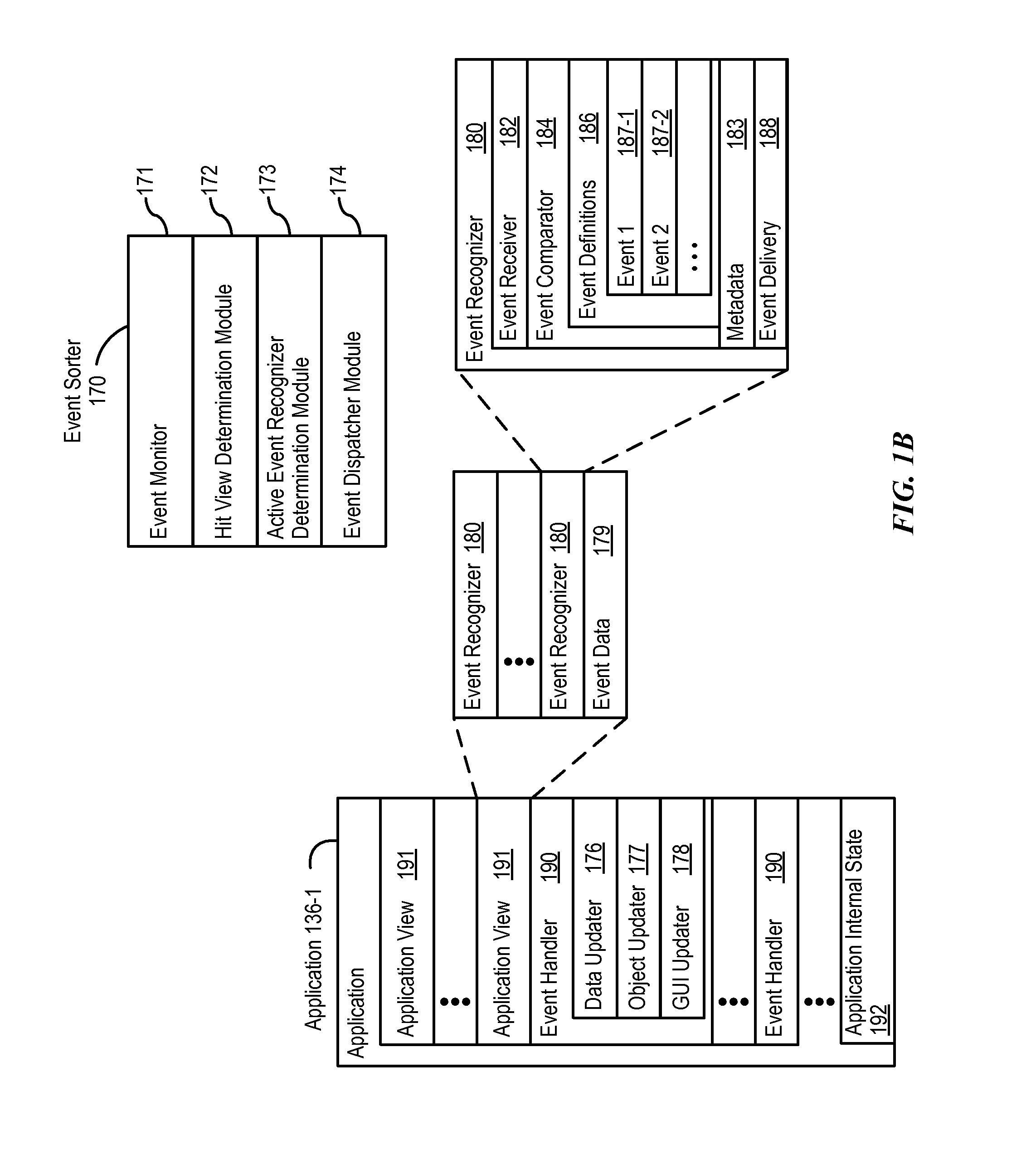
[0030]It is desirable for a device to provide efficient, user-friendly procedures for displaying timing data (e.g., displaying lap times and their representations), allowing for user customization of timing data display parameters (e.g., allowing for user modification of timescales of timing elements), and inputting timing values (e.g., allowing for robust entry of timer settings). Below, FIGS. 1A-1B, 2, 3, 4A-4B, and 5A-5B provide a description of exemplary devices that optionally perform lap time representing, timescale adjusting and timer setting techniques. FIGS. 6-8 illustrate exemplary user interfaces involved in the above techniques. The user interfaces in the figures are also used to illustrate the l...


PUM


Abstract

An electronic device may display a first lap time representation, and may move the first lap time representation in accordance with a first amount of elapsed time. While moving the first lap time representation, the electronic device may detect a lap input. In response to the lap input, the electronic device may cease movement of the first lap time representation, display a second lap time representation, and move the second lap time representation in accordance with a second amount of elapsed time. A relative positioning of the first lap time representation and the second lap time representation may correspond to a difference between a first lap time and a second lap time. In some embodiments, the electronic device may update the timescales of lap time representation(s) in accordance with a rotational input. In some embodiments, the electronic device may update a timer duration setting in accordance with a rotational input.

Description

CROSS-REFERENCE TO RELATED APPLICATIONS[0001]This application claims priority to U.S. Provisional Patent Application No. 62 / 044,979, entitled “STOPWATCH AND TIMER USER INTERFACES,” filed Sep. 2, 2014, and U.S. Provisional Patent Application No. 62 / 129,825, entitled “STOPWATCH AND TIMER USER INTERFACES,” filed Mar. 7, 2015, which are hereby incorporated by reference in their entirety.[0002]This application relates to: U.S. Provisional Patent Application entitled “Context-Specific User Interfaces,” filed Sep. 2, 2014, naming Christopher Wilson as the inventor, International Patent Application Serial No. PCT / US2013 / 040061, entitled “Device, Method, and Graphical User Interface for Displaying User Interface Objects Corresponding to an Application,” filed May 8, 2013, and International Patent Application Serial No. PCT / US2013 / 069483, entitled “Device, Method, and Graphical User Interface for Transitioning Between Touch Input to Display Output Relationships,” filed Nov. 11, 2013. The cont...

Claims


Application Information

Patent Timeline
Patent Type & Authority Applications(United States)
IPC IPC(8): G06F3/0484G04F10/00G06F3/0482G06F3/0488
CPCG06F3/0484G06F3/0482G06F3/0488G04F10/00H04M1/72522A63B24/00G07C1/22G07C1/24G06F3/04883H04M2250/22G06F3/04817G06F3/04842G06F3/0481G06F3/0485
Inventor WILSON, ERIC, LANCEWILSON, CHRISTOPHERDASCOLA, JONATHAN, R.BUTCHER, GARY, IANCHAUDHRI, IMRANDYE, ALAN, C.LEMAY, STEPHEN, O.MARIC, NATALIAYANG, LAWRENCE, Y.
Owner APPLE INC
Why Eureka
Try Eureka