Reduced glare surgical microscope and associated devices, systems, and methods

a surgical microscope and glare reduction technology, applied in the field of surgical microscopes, can solve the problems of difficult for surgeons to see patients' eyes, glare caused by light sources directing light at the fluid-air interface, and remains, so as to limit the transmission of light associated with the effect of glar

Active Publication Date: 2016-03-31
ALCON INC
View PDF2 Cites 22 Cited by
  • Summary
  • Abstract
  • Description
  • Claims
  • Application Information

AI Technical Summary

Benefits of technology

[0008]Consistent with some embodiments, a method of operating an ophthalmic surgical microscope positioned in an optical pathway between a surgical field and an observer includes: receiving light reflected from the surgical field at an image sensor of the ophthalmic surgical microscope; processing the received light to generate image data; identifying portions of the image data representative of glare from the surgical field; and controlling an optical element positioned in the optical pathway to limit the transmission of light associated with the glare.

Problems solved by technology

One impediment to a doctor's ability to view the patient's anatomy through the surgical microscope is glare from the surgical field.
The glare from the fluid-air interface is problematic for several reasons.
For example, the glare can saturate the surgeon's visual field and make it difficult for the surgeon to see the patient's eye.
This can be disruptive to the surgical procedure because it takes extra time for the lingering effects from the glare to pass and for the surgeon to see clearly again.
However, the glare caused by the light source directing light at the fluid-air interface remains.

Method used


Image

  • Reduced glare surgical microscope and associated devices, systems, and methods
  • Reduced glare surgical microscope and associated devices, systems, and methods
  • Reduced glare surgical microscope and associated devices, systems, and methods

Examples


Embodiment Construction

[0026]In the following description specific details are set forth describing certain embodiments. It will be apparent, however, to one skilled in the art that the disclosed embodiments may be practiced without some or all of these specific details. The specific embodiments presented are meant to be illustrative, but not limiting. One skilled in the art may realize other material that, although not specifically described herein, is within the scope and spirit of this disclosure.

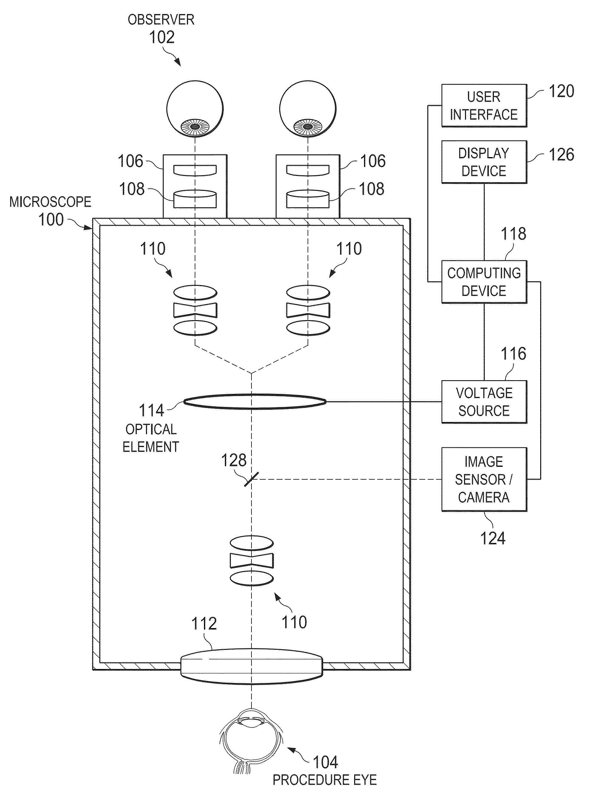
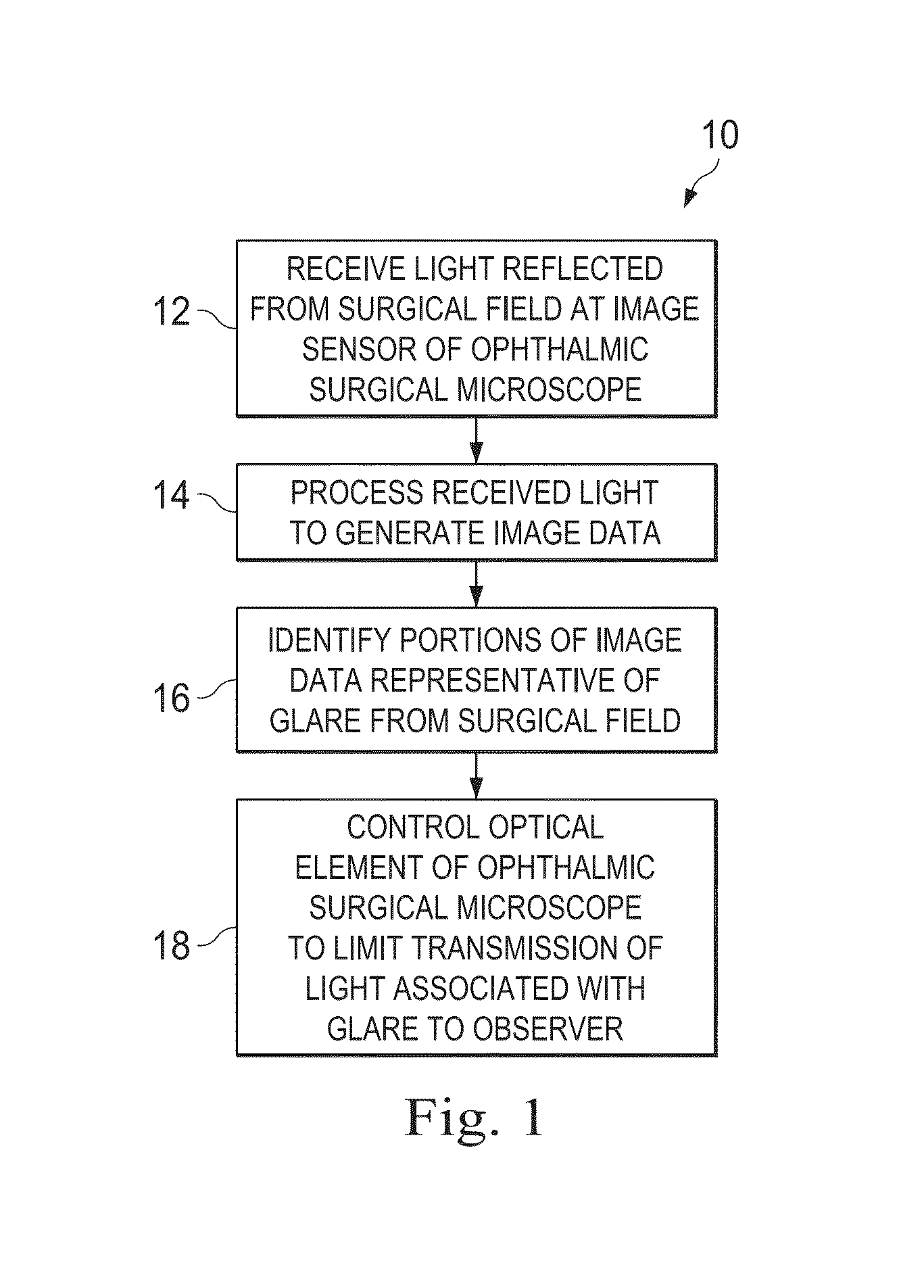
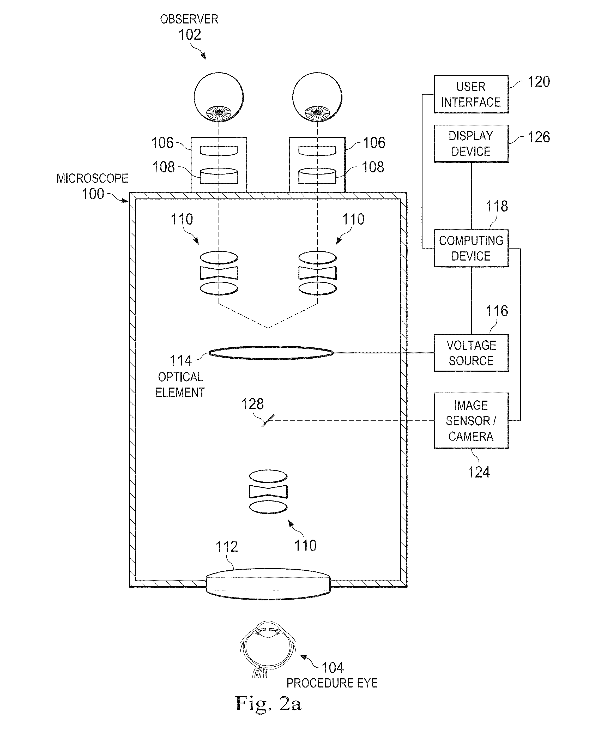
[0027]The present disclosure describes an ophthalmic surgical microscope with an image sensor / camera and a controllable optical element. Light reflected from the surgical field can be received at the image sensor / camera. A computing device in communication with the image sensor / camera can determine portions of the light associated with glare from the surgical field. The computing device can generate a control signal to cause the optical element to selectively limit the transmission of light associated with the...


PUM

PropertyMeasurementUnit
transmissionaaaaaaaaaa
voltageaaaaaaaaaa
brightnessaaaaaaaaaa

Abstract

Devices, systems, and methods for glare reduction in surgical microscopy are provided. A method of operating a surgical microscope may include: receiving light reflected from the surgical field at an image sensor; processing the received light to generate image data; identifying portions of the image data representative of glare; and controlling an optical element to limit the transmission of light associated with the glare. A surgical microscope may include: an image sensor configured to receive light reflected from the surgical field, a computing device, and an optical element. The computing device may be configured to: identify portions of the light received at the image sensor associated with glare and generate a control signal to limit the transmission of the light associated with the glare. The optical element may be configured to selectively limit the transmission of the light associated with the glare in response to the control signal.

Description

TECHNICAL FIELD[0001]Embodiments disclosed herein are related to surgical microscopes. More specifically, embodiments described herein relate to microscopes including an optical element controllable to selectively reduce glare from light reflected from a surgical field.RELATED ART[0002]Doctors can use surgical microscopes during surgical procedures to see fine details of a patient's anatomy (e.g., details of a patient's eye during ophthalmic surgical procedure). A successful procedure can depend on the doctor's ability to view the patient's anatomy clearly using the microscope. One impediment to a doctor's ability to view the patient's anatomy through the surgical microscope is glare from the surgical field.[0003]In some instances of ophthalmic surgery, glare occurs as a result of a fluid-air interface in a patient's eye. For example, a vitreoretinal surgery involving treatment of retinal detachment or a macular hole can include a fluid-air exchange. During the fluid-air exchange, s...

Claims


Application Information

Patent Timeline
Patent Type & Authority Applications(United States)
IPC IPC(8): A61B3/15A61B3/00A61B3/13G02B21/00G02F1/13G02F1/133
CPCA61B3/156G02B21/0012A61B3/0025G02F1/13318A61B3/13G02F1/1313G02B27/0018A61B3/132A61B3/158
Inventor HEEREN, TAMMO
Owner ALCON INC
Why Eureka
Try Eureka