Blinds for adjusting illumination made of thick material

a blind material and thick material technology, applied in the field of roll type blinds, can solve the problems of invading privacy, and increasing the outer diameter of the blind material, so as to increase the lifespan of the blind material

Inactive Publication Date: 2010-10-05
BYEON TAE WOONG
View PDF13 Cites 42 Cited by
  • Summary
  • Abstract
  • Description
  • Claims
  • Application Information

AI Technical Summary

Benefits of technology

[0023]According to the blind for adjusting height and brightness made of a thick blind material of the present invention as described above, an end of a rotation piece, to which the blind material is fixed, is connected to an outer peripheral surface of the blind material all the time regardless of an outer diameter, that is, a winding amount of the blind material on the winding rod, so that an interval between an inner blind material and an outer blind material is kept uniformly. Therefore, curling of the outer blind material on the winding rod may be prevented when the blind material is wound on the winding rod completely. Further, the amount of light transmission of the blind material may be properly controlled even when the blind material is completely released from the winding rod.
[0024]If a fiber protecting element is provided in a lower part of a rotation piece, the fiber protecting element may prevent generation of static electricity caused by friction between the blind material and the rotation piece, generation of contact mark caused by contact between the blind material and the rotation piece, and the generation of naps in advance, thereby expanding the lifespan of the blind material.

Problems solved by technology

Therefore, the room is exposed to the outside via the window, causing invasion of privacy.
The prior art blind for controlling the height and brightness thereof by winding or releasing the blind material 7 on or from the winding rod 4 as described above has, however, a problem that an outer diameter of the blind material 7 wound on the winding rod 4 becomes increased when a thick blind material 7 is employed for a window of a predetermined height for the purpose of insulation in winter time, even though a thin blind material has no problems for a window of the same height.

Method used


Image

  • Blinds for adjusting illumination made of thick material
  • Blinds for adjusting illumination made of thick material
  • Blinds for adjusting illumination made of thick material

Examples


Embodiment Construction

[0035]Now the preferred embodiments according to the present invention will be described with reference to the accompanying drawings.

[0036]FIG. 5 and FIG. 6 are longitudinal cross-sectional views respectively showing the blind for adjusting height and brightness made of a thick blind material according to a preferred embodiment of the present invention, FIG. 7 and FIG. 8 are longitudinal cross-sectional views respectively showing a rotation element employed in the blind according to another preferred embodiment of the present invention, and FIG. 9 is a longitudinal cross-sectional view showing a fiber protecting element employed in the blind according to a further preferred embodiment of the present invention.

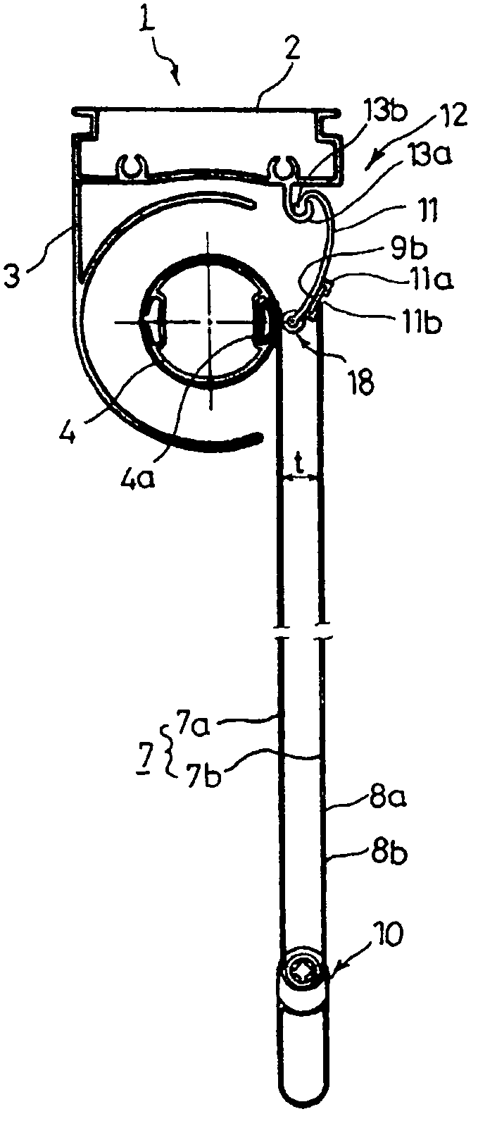
[0037]According to the present invention, a blind material 7 has an end fitted into a mounting part 4a of a winding rod 4 to be fixed thereto. An upper supporting bar 2 is mounted with a rotation piece 11 at an upper end, and the rotation piece 11 rotates by a rotation element ...


PUM


Abstract

The present invention relates to a roll type blind mounted in a window for preventing light from being introduced from the outside or leaking from the inside of a room. In the blind for adjusting height and brightness made of a thick blind material according to the present invention, an inner blind material and an outer blind material of the thick blind material hang down in a tensed state by a pre-weight element and they always keep an equal width therebetween.

Description

TECHNICAL FIELD[0001]The present invention relates to a roll type blind mounted on a window for preventing light from being introduced from the outside or leaking from the inside of a room, and more particularly to a blind for adjusting height and brightness made of thick blind material, wherein an inner blind material and an outer blind material of the thick blind material hang down in a tensed state by a pre-weight element and they always keep an equal width therebetween.BACKGROUND ART[0002]In general, a shield element is mounted to an inside of a window for blocking a room from the outside, wherein the shield element may be opened or closed to control an intensity of illumination by external light, for example, sunlight.[0003]Such a shield element is to be inevitably moved right and left, or up and down partially for the control of the illumination of a room. Therefore, the room is exposed to the outside via the window, causing invasion of privacy.[0004]Therefore, there has been ...

Claims


Application Information

Patent Timeline
Patent Type & Authority Patents(United States)
IPC IPC(8): E06B9/40
CPCE06B9/40E06B9/64E06B2009/2405E06B2009/2458
Inventor BYEON, TAE WOONG
Owner BYEON TAE WOONG
Why Eureka
Try Eureka