Optical connector for jacketed cables

a technology of optical connectors and jacketed cables, applied in the field of optical connectors, can solve the problems of incompatibility of hybrid splice connectors with standard connector formats, inconvenient installation of field installations, and awkward process and time-consuming field performance, etc., to achieve repeatability, simplify the installation process, and ensure the effect of fiber insertion accuracy

Active Publication Date: 2014-09-25
CORNING RES & DEV CORP
View PDF3 Cites 20 Cited by
  • Summary
  • Abstract
  • Description
  • Claims
  • Application Information

AI Technical Summary

Benefits of technology

[0013]In another aspect, an assembly tool for repeatable, accurate fiber insertion into the optical fiber connector is provided. The assembly tool allows the setting of a precise protrusion length of fiber from the end face of the ferrule to simplify the installation process. The fiber connector termination assembly tool includes a base having a connector mount to receive the optical connector and a protrusion setting station having a protrusion setting jig, wherein the base further includes a pivotably attached actuation lever configured to provide for the sequential setting of a protrusion length of the optical fiber from an end of ferrule disposed in the optical connector and to actuate a fiber gripping mechanism disposed in the optical connector. The assembly tool also includes a fiber holder assembly configured to be slidably received in a guide channel of the base, the fiber holder assembly including a fiber clamp to secure the jacketed fiber cable in the fiber holder assembly and first and second pivotably attached lids, the first lid mounted on a first shuttle plate and the second lid mounted on a second shuttle plate configured to independently slide in an axial direction, the first and second lids preventing the optical fiber from curling during the termination process.

Problems solved by technology

However, commercially available optical connectors are not well suited for field installations.
This process can be awkward and time consuming to perform in the field.
However, these hybrid splice connectors are not compatible with standard connector formats and require significant piecewise assembly of the connector in the field.
The handling and orientation of multiple small pieces of the connector can result in incorrect connector assembly that may either result in decreased performance or increase the chance of damaging the fiber.

Method used


Image

  • Optical connector for jacketed cables
  • Optical connector for jacketed cables
  • Optical connector for jacketed cables

Examples


Embodiment Construction

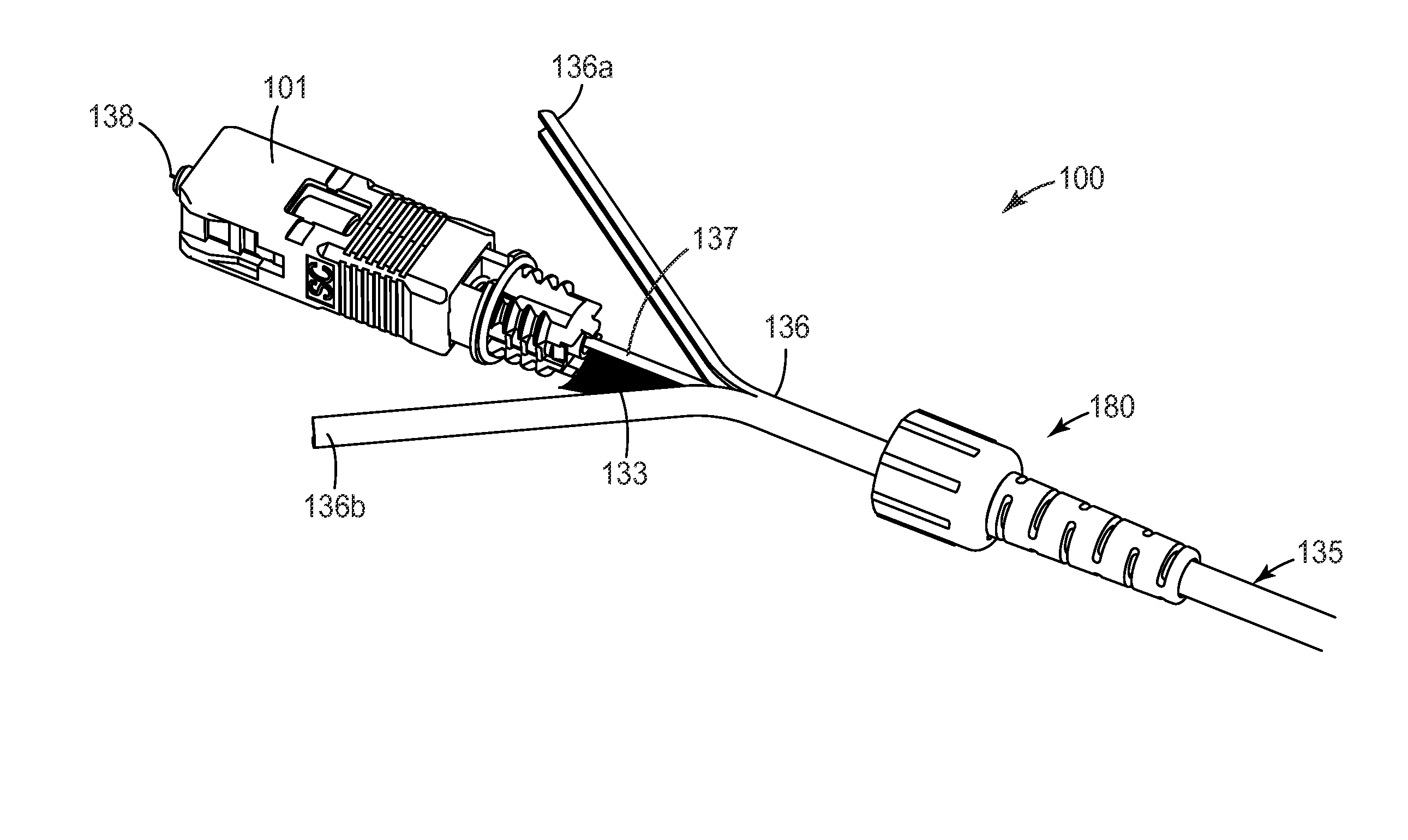
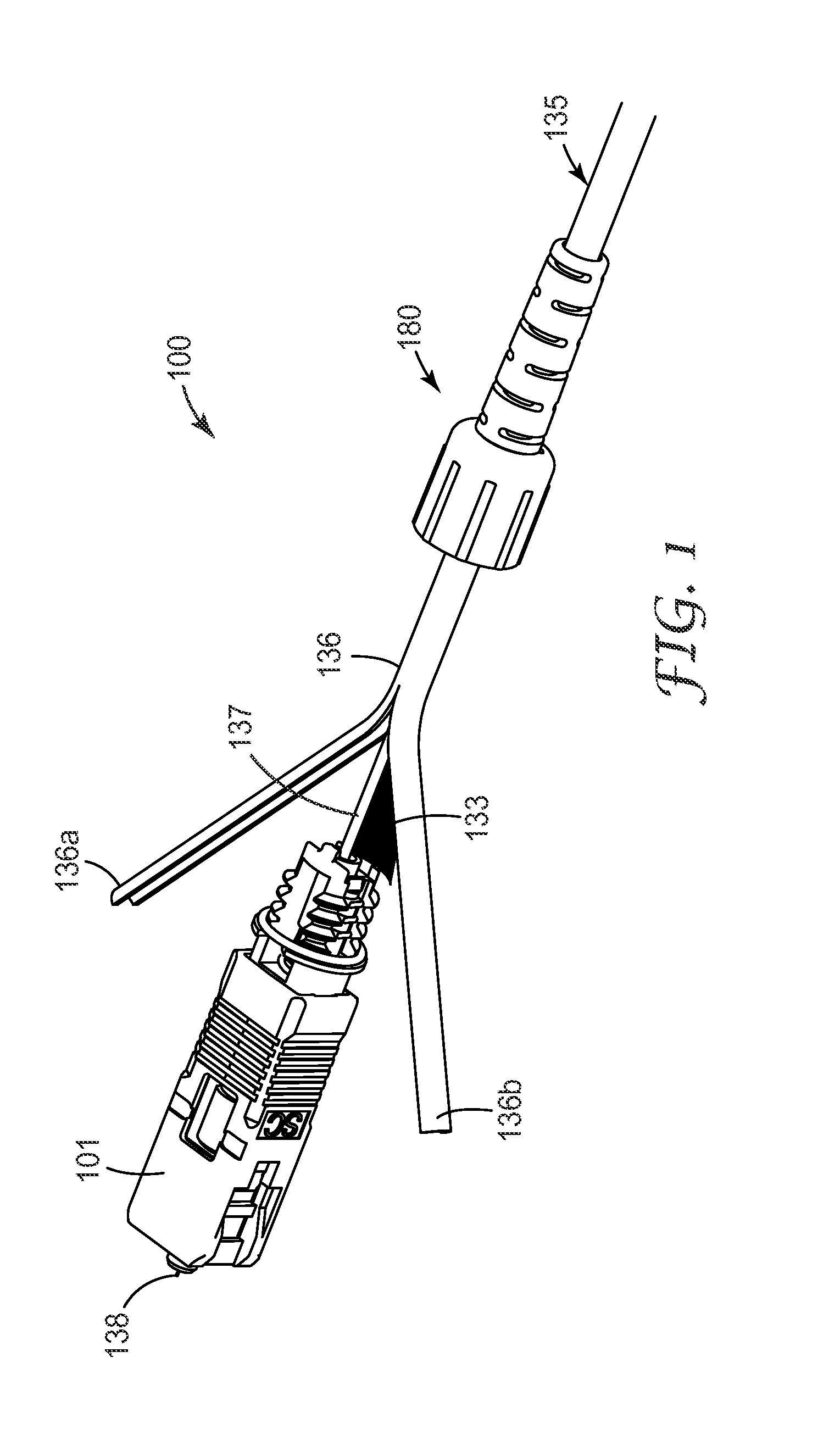
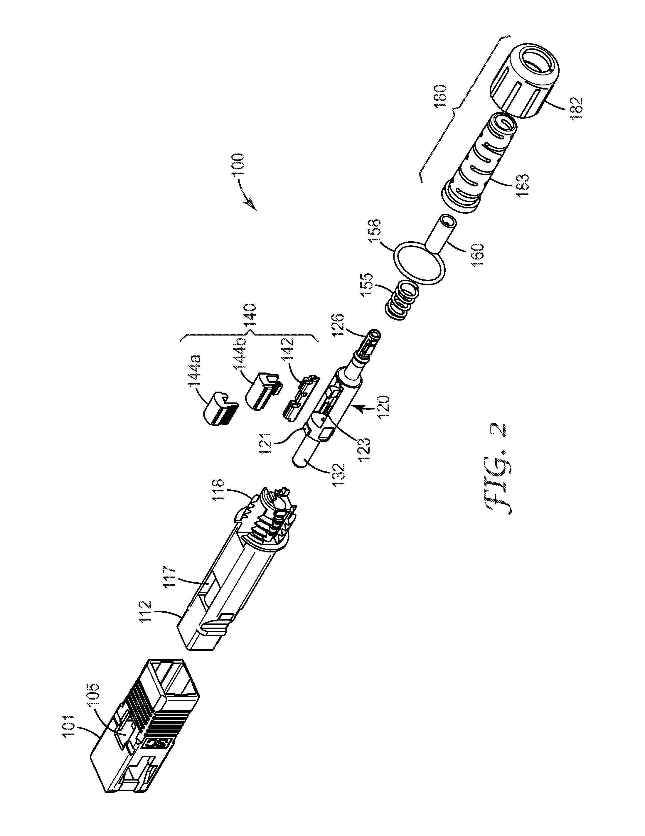
[0025]The present invention is directed to an optical connector. In particular, the optical connector of the exemplary embodiments is of compact length and is capable of straightforward field termination of jacketed optical fiber cables having cable diameters of between about 1.5 mm to about 3 mm. The structure of the optical connector provides for retention of cable strength members and the cable jacket in a straightforward manner suitable for field termination. Further, with the straightforward connector termination platform and procedure described herein, reduced assembly times in field termination applications can be accomplished. The exemplary connector(s) described herein can be readily installed and utilized for fiber network installations, as well as in other applications requiring field mounted connectors.

[0026]According to an exemplary embodiment of the present invention, an optical fiber connector 100 is shown in isometric view (in a pre-finished state) in FIG. 1, in expl...


PUM


Abstract

An optical connector for terminating a jacketed optical fiber cable comprises a housing configured to mate with a receptacle. The connector also includes a collar body disposed in the housing, the collar body securing, at a first end, a ferrule. The collar body includes a gripping mechanism disposed in a second portion of the collar body. The collar body further includes a buffer clamp configured within a third portion of the collar body, the buffer clamp configured to clamp at least a portion of a buffer cladding of the optical fiber upon actuation. The optical connector also includes a backbone to retain the collar body within the housing. The backbone includes a mounting structure surrounding a central bore at one end of the backbone, the mounting structure having at least one pocket region configured to receive a slit portion of the cable jacket. A fiber connector termination and assembly tool is also provided.

Description

BACKGROUND OF THE INVENTION[0001]1. Field of the Invention[0002]The present invention is directed to an optical connector.[0003]2. Related Art[0004]Mechanical optical fiber connectors for the telecommunications industry are known. For example, LC, ST, FC, and SC optical connectors are widely used.[0005]However, commercially available optical connectors are not well suited for field installations. Typically, an adhesive is required to mount these types of connectors on to an optical fiber. This process can be awkward and time consuming to perform in the field. Also post-assembly polishing requires that the craftsman have a higher degree skill.[0006]Also known are hybrid optical splice connectors, as described in JP Patent No. 3445479, JP Application No. 2004-210251 (WO 2006 / 019516) and JP Application No. 2004-210357 (WO 2006 / 019515). However, these hybrid splice connectors are not compatible with standard connector formats and require significant piecewise assembly of the connector i...

Claims


Application Information

Patent Timeline
Patent Type & Authority Applications(United States)
IPC IPC(8): G02B6/38
CPCG02B6/381G02B6/3846G02B6/3898G02B6/3857G02B6/3888G02B6/38875G02B6/36
Inventor PRATT, JEROME A.PEPIN, RONALD P.SAWICKI, JOSEPH C.BALL, SHIRLEY E.RAIDER, WESLEY A.LARSON, DONALD K.
Owner CORNING RES & DEV CORP
Why Eureka
Try Eureka