Aero-engine air rotational flow plasma igniter

An aero-engine and plasma technology, which is used in engine ignition, engine components, machines/engines, etc., can solve the problems of low working environment pressure, short life, and high electrode temperature, achieve strong electron emission capability, and improve stability.

Inactive Publication Date: 2013-09-04
AIR FORCE UNIV PLA
View PDF5 Cites 37 Cited by
  • Summary
  • Abstract
  • Description
  • Claims
  • Application Information

AI Technical Summary

Problems solved by technology

[0007] In order to overcome the disadvantages existing in the prior art that the volume and weight are large, the electrode temperature is high, there is no cooling, the life is short, and the working environment pressure is low, and it is not suitable for use in the high temperature and high pressure environment of the aeroengine combustion chamber, the present invention proposes Air swirl plasma igniter for aero-engine

Method used


Image

  • Aero-engine air rotational flow plasma igniter
  • Aero-engine air rotational flow plasma igniter
  • Aero-engine air rotational flow plasma igniter

Examples


Embodiment 1

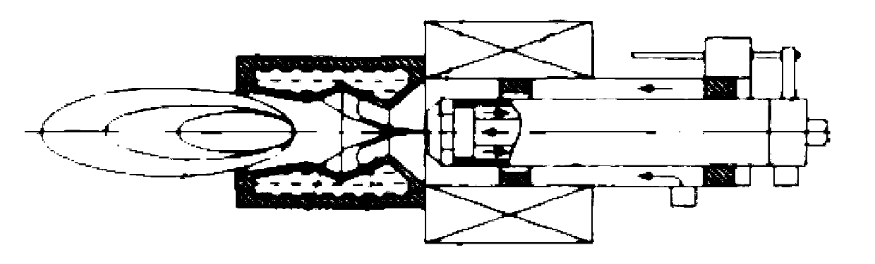
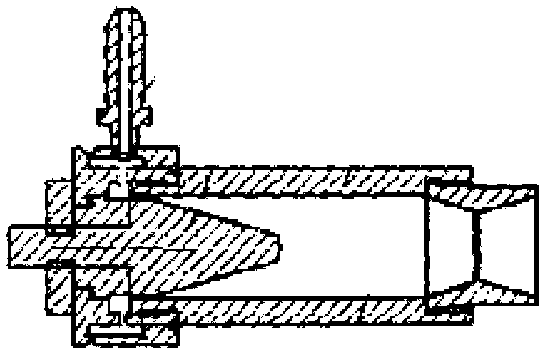
[0035] This embodiment is an air swirling plasma jet igniter for an aeroengine combustion chamber, comprising a housing 1, an air intake pipe 2, an anode sleeve 3, an insulating sleeve 4, a cathode mounting seat 5, a support sleeve 6, a cathode 7 and a rotary Streamer 8. Wherein, both the insulating sleeve 4 and the supporting sleeve 6 are installed in the casing 1 . The insulating sleeve 4 is located on one side of the inner partition of the housing, and the insulating sleeve 4 is in interference fit with the housing 1; the supporting sleeve 6 is located on the other side of the inner partition of the housing, and the supporting An air chamber is formed between the outer surface of the sleeve 6 and the inner surface of the casing 1 . One end of the supporting sleeve 6 passes through the central hole of the inner partition and is embedded in the groove on the end face of the insulating sleeve 4 . The anode sleeve 3 is fitted on the casing at the end of the housing 1 with the...

Embodiment 2

[0046] This embodiment is an air swirling plasma jet igniter for an aeroengine combustion chamber, comprising a housing 1, an air intake pipe 2, an anode sleeve 3, an insulating sleeve 4, a cathode mounting seat 5, a support sleeve 6, a cathode 7 and a rotary Streamer 8. Wherein, both the insulating sleeve 4 and the supporting sleeve 6 are installed in the casing 1 . The insulating sleeve 4 is located on one side of the inner partition of the housing, and the insulating sleeve 4 is in interference fit with the housing 1; the supporting sleeve 6 is located on the other side of the inner partition of the housing, and the supporting An air chamber is formed between the outer surface of the sleeve 6 and the inner surface of the casing 1 . One end of the supporting sleeve 6 passes through the central hole of the inner partition and is embedded in the groove on the end face of the insulating sleeve 4 . The anode sleeve 3 is fitted on the casing at the end of the housing 1 with the...


PUM


Abstract

Provided is an aero-engine air rotational flow plasma igniter. An insulating sleeve and a supporting sleeve are installed inside a shell, the insulating sleeve is arranged on one side of a separating plate inside the shell, the supporting sleeve is arranged inside the shell, and an air chamber is formed between the outer surface of the supporting sleeve and the inner surface of the shell. An anode sleeve is sleeved at one end, provided with the supporting sleeve, of the shell. A swirler is arranged inside the anode sleeve, and the end surface of the swirler makes contact with the end surface of the supporting sleeve. A cathode installation base is arranged inside the insulating sleeve, and the end surface of the cathode installation base makes contact with a cathode binding post in a coaxial cable. The external thread end of a cathode is fixed inside the cathode installation base and sequentially penetrates through the supporting sleeve and the swirler from top to bottom, and the arc end of the cathode extends out of the lower end surface of the swirler. The aero-engine air rotational flow plasma igniter does not change the structure and the position of an electric spark igniter originally installed in an engine combustor, penetrates through the outer duct of an engine, is installed on the outer wall of the combustor vertically, improves reliability of products, and has the advantages of being small in size, light in weight, simple in structure, and convenient to use and maintain.

Description

technical field [0001] The invention relates to plasma ignition and combustion enhancement technology in the field of aviation power. The plasma igniter uses air as the working medium, and the working medium is punctured by high voltage to form an arc discharge, which is ejected from the nozzle of the igniter in the form of a high-temperature jet to form a high-temperature flame. The high-temperature, high-speed plasma jet rich in active particles is used to ignite the oil-air mixture in the combustion chamber of the aero-engine. Background technique [0002] With the continuous improvement of the performance of fighter jets, higher requirements are put forward for the starting characteristics of aero-engine combustion chambers under high maneuvering and high-altitude working conditions. At present, the high-energy ignition devices used in aero-engines at home and abroad usually use semiconductor nozzles, which have been working in harsh high-temperature environments for a l...

Claims


Application Information

Patent Timeline
Patent Type & Authority Applications(China)
IPC IPC(8): F02P23/00
Inventor 何立明赵兵兵杜宏亮于锦禄张华磊宋振兴刘兴建
Owner AIR FORCE UNIV PLA
Why Eureka
Try Eureka