
An internal grinding wheel and internal cooling system

A cooling system and internal grinding technology, applied in the field of grinding, can solve the problems of grinding fluid waste, affecting the working environment, and limited centrifugal force, and achieve the effects of reducing production costs, improving the working environment, and reducing repeated rolling

Active Publication Date: 2017-07-14
CHANGSHA UNIVERSITY OF SCIENCE AND TECHNOLOGY
View PDF6 Cites 0 Cited by
  • Summary
  • Abstract
  • Description
  • Claims
  • Application Information

AI Technical Summary

Problems solved by technology

However, this cooling method has the following defects: ①The liquid supply method is to input the grinding fluid into the radial hole of the grinding wheel, and then use the centrifugal force generated by the high-speed rotation of the grinding wheel to throw the grinding fluid in the radial hole into the grinding area. The effect of centrifugal force is limited, so the flow of grinding fluid into the grinding zone is very limited and the pressure is insufficient
②The flow and pressure of the grinding fluid entering the grinding area cannot be adjusted, and the grinding fluid is sprayed along the circumference of the grinding wheel, and most of the sprayed grinding fluid does not enter the grinding area, resulting in waste of grinding fluid and affecting work surroundings
③The outer circumferential working surface of the grinding wheel has radial holes, so it is still intermittent grinding in essence, and the grinding wheel will inevitably have large periodic vibrations, which will affect the grinding quality
④Considering the structural strength of the grinding wheel, the number of radial openings on the working surface is very limited, so it is difficult to ensure that within the contact length of the grinding wheel and the workpiece during grinding, there are radial holes to provide grinding fluid for the grinding center area. Dry grinding may also occur under extreme conditions
⑤ The radial drilling process is complicated, and the manufacturing cost of the grinding wheel is high

Method used


Image

  • An internal grinding wheel and internal cooling system
  • An internal grinding wheel and internal cooling system
  • An internal grinding wheel and internal cooling system

Examples


Embodiment Construction

[0035] The technical solution of the present invention will be further described below in conjunction with the accompanying drawings.

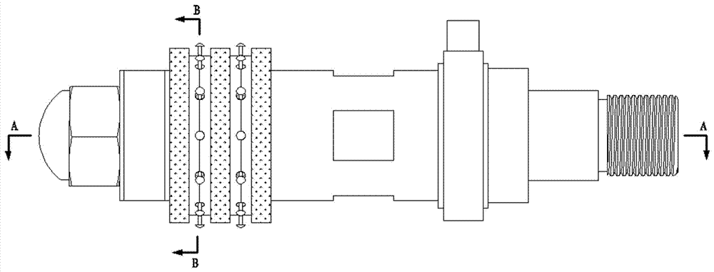
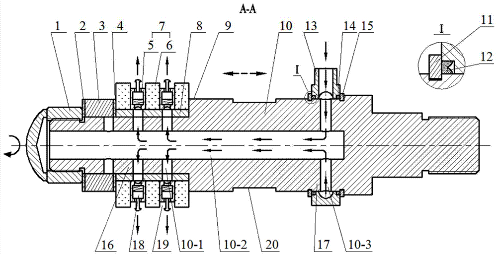
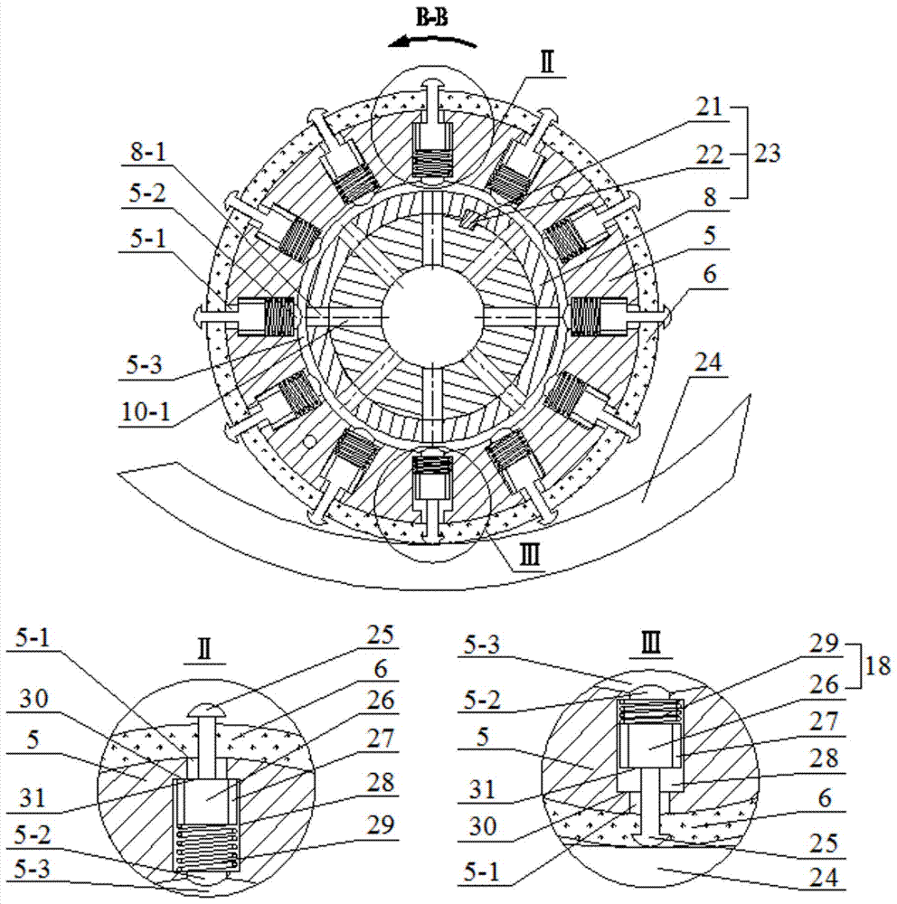
[0036] An internal grinding wheel and an internal cooling system of the present invention mainly include a sandwich grinding wheel 7 , a liquid supply end 17 , a main shaft 10 , a liquid output end 16 , a flow regulating device 23 and an automatic flow direction regulating device 18 . The high-pressure grinding fluid flows through the liquid inlet 13-1, the annular groove 13-2, the main shaft liquid inlet hole 10-3, the main shaft cavity 10-2, the main shaft liquid outlet hole 10-1, and the shaft sleeve small hole 8- 1. Spacer ring groove 5-3, spacer ring liquid flow channel 34, and then flow into the grinding center area of ​​sandwich grinding wheel 7 and workpiece 24 through liquid outlet channel 19, forming a sealed liquid flow channel. The following describes the implementation and features of the present invention step by step according t...


PUM


Abstract

The invention discloses an internal grinding wheel and an internal cooling system. The internal grinding wheel comprises a sandwich grinding wheel, a liquid supply end, a main shaft, a liquid discharging end, a flow regulating device and an automatic flow direction regulating device, wherein the sandwich grinding wheel consists of grinding rings and isolating rings which are alternately arranged; the isolating rings do not involve with grinding; the liquid supply end comprises a retainer ring, a sealing ring and a liquid supply ring; the liquid supply ring has clearance fit with the main shaft and is axially located by the retainer ring; the liquid discharging end comprises a shaft sleeve small hole, an isolating ring liquid flowing passage and a liquid discharging passage; the main shaft is communicated with the liquid supply end and the liquid discharging end; the flow regulating device comprises a key, a shaft sleeve and a shaft sleeve key slot; the flux and pressure of grinding liquid can be regulated by regulating the circumferential position of the shaft sleeve and the circumferential position of the main shaft; the automatic flow direction regulating device comprises a switch piston and a spring; the automatic flow direction regulating device can be controlled to start or stop by a piston dome on the switch piston, so that automatic regulation on liquid flow direction is realized. The internal grinding wheel disclosed by the invention has the advantages of efficiently utilizing the grinding liquid, reducing the grinding temperature and improving the grinding quality.

Description

technical field [0001] The invention belongs to the field of grinding processing, in particular to an inner circular grinding wheel and an inner cooling system. Background technique [0002] Compared with other mechanical processing methods, grinding has the advantages of high precision, wide application range, good surface quality, and excellent self-sharpening performance. According to statistics, 25% of enterprises believe that grinding is the main processing technology they use, and grinding machines account for as high as 42% of machine tools in enterprises. However, the characteristics of the grinding process determine that its specific energy is very high, and most of the grinding energy is converted into heat energy, which often causes the temperature in the grinding area to rise sharply. If the grinding temperature is too high, it will cause burns and burns on the workpiece. Increased wheel wear. Moreover, most of the grinding debris generated during grinding adhe...

Claims


Application Information

Patent Timeline
Patent Type & Authority Patents(China)
IPC IPC(8): B24B5/36B24B57/02B24B55/03
CPCB24B5/36B24B55/03B24B57/02
Inventor 毛聪梁昶张健张明军唐昆李伟胡永乐卢继
Owner CHANGSHA UNIVERSITY OF SCIENCE AND TECHNOLOGY
Learn More