Electromagnetic fixed power cabinet based on wind power generation

It is a fixed type and power cabinet technology, which is applied in the substation/power distribution device shell, electrical components, substation/switch layout details, etc. It can solve the problems of long installation time, time-consuming and labor-intensive installation, and reduced work efficiency. The effect of increasing the connection effect, saving power resources, and improving the installation quality

Inactive Publication Date: 2021-01-08
上海旌磊技术中心
View PDF0 Cites 0 Cited by
  • Summary
  • Abstract
  • Description
  • Claims
  • Application Information

AI Technical Summary

Problems solved by technology

[0002] The full name of reactive power compensation is reactive power compensation. It is a technology that can improve the power factor of the power grid in the power supply system, reduce the loss of power supply transformers and transmission lines, improve power supply efficiency, and improve the power supply environment. The current power reactive power Most of the compensation cabinets are fixed on the roadside by concrete, which effectively prevents the tilting of the power reactive power compensation cabinets. However, the installation of the current power reactive power compensation cabinets is time-consuming and laborious, and the installation is difficult
[0003] Due to the light weight of the power reactive power compensation cabinet and the relatively precise internal parts, if the cabinet falls over, the internal parts will be damaged due to impact. Therefore, in order to prevent the cabinet from falling over, the bottom of the cabinet is mostly The concrete and the ground are fixed together, so more materials are required for installation, and it is difficult to transport, and the installation consumes more time, which greatly reduces work efficiency

Method used


Image

  • Electromagnetic fixed power cabinet based on wind power generation
  • Electromagnetic fixed power cabinet based on wind power generation
  • Electromagnetic fixed power cabinet based on wind power generation

Examples


Embodiment Construction

[0021] The following will clearly and completely describe the technical solutions in the embodiments of the present invention with reference to the accompanying drawings in the embodiments of the present invention. Obviously, the described embodiments are only some, not all, embodiments of the present invention. Based on the embodiments of the present invention, all other embodiments obtained by persons of ordinary skill in the art without making creative efforts belong to the protection scope of the present invention.

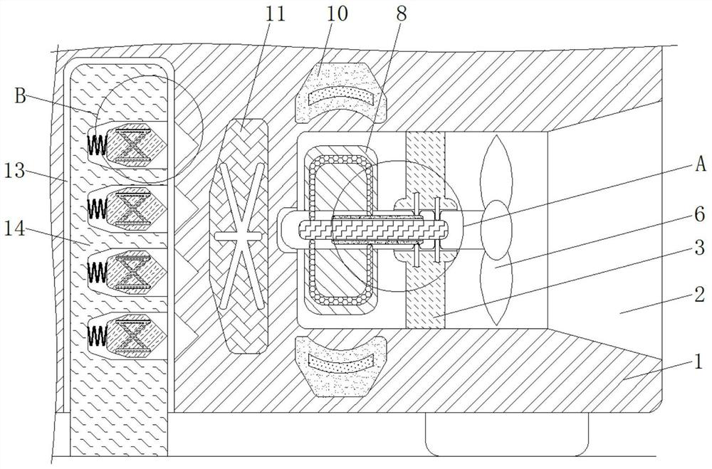
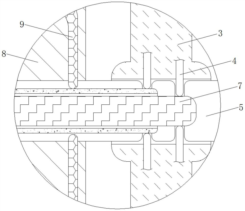
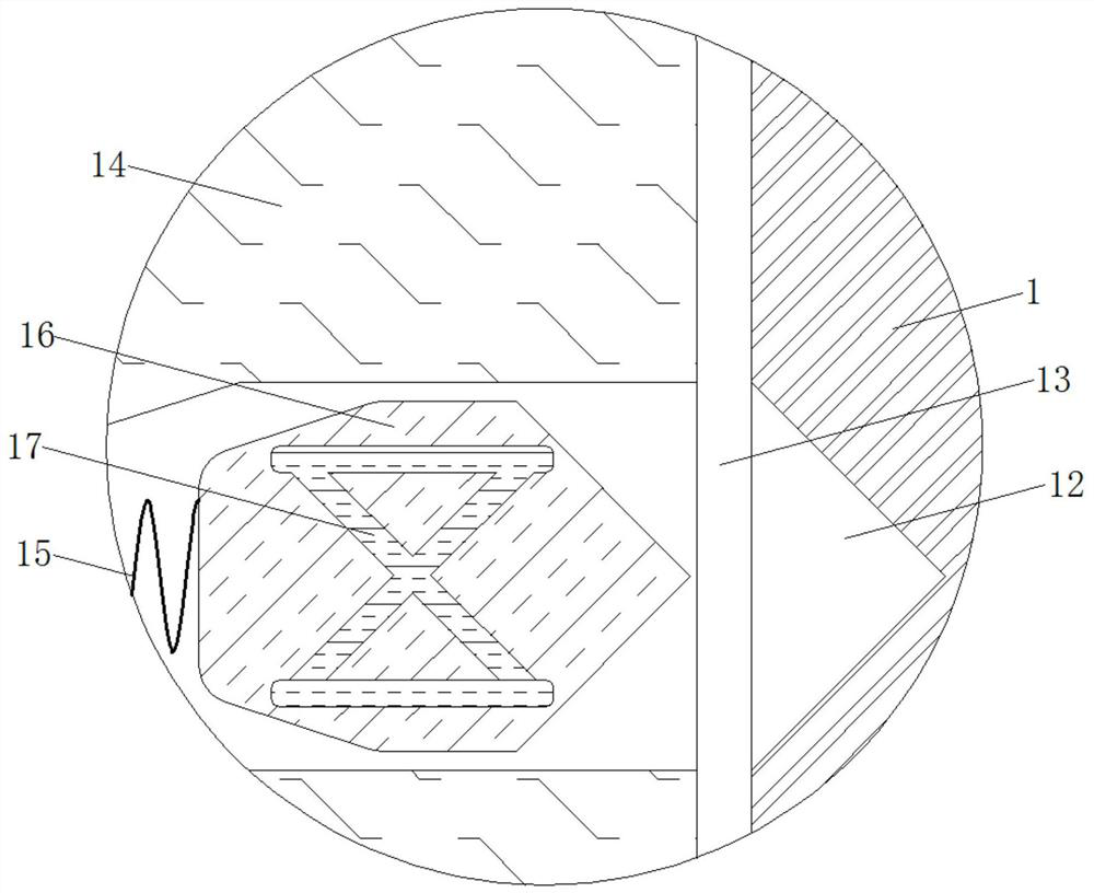
[0022] see Figure 1-5 , an electromagnetic fixed power cabinet based on wind power generation, including a cabinet body 1, the material of the cabinet body 1 is a hard high-strength material and the cabinet body 1 does not have electrical conductivity and magnetic conductivity, and the cabinet body 1 has fixed components and To protect internal parts, the size of the air inlet 2 is smaller than the size of the cabinet body 1 and the shape of the air inlet 2 i...


PUM


Abstract

The invention provides an electromagnetic fixed power cabinet based on wind power generation, and relates to the technical field of power reactive compensation. The electromagnetic fixed power cabinetcomprises a cabinet body, wherein an air inlet is formed in the bottom of the outer side of the cabinet body, a bracket is fixedly connected to the inner wall of the bottom of the cabinet body and close to the middle of the air inlet, conductive blocks are fixedly connected to the inner wall of the bracket, a rotating shaft is movably connected to the middle of the bracket, a fan is movably connected to the outer side of the rotating shaft, electric connection blocks are fixedly connected to the middle of the rotating shaft, and evenly-distributed connecting blocks are fixedly connected to the left side of the outer side of the rotating shaft. According to the electromagnetic fixed power cabinet based on wind power generation, through cooperative use of the electromagnets and the magneticblocks, when the cabinet body is subjected to wind power, the generated current is gradually increased along with increase of the wind power, so that the magnetism generated by the electromagnets isalso increased, the magnetic blocks are subjected to larger magnetic attraction force, and the clamping effect of the clamping blocks and the clamping grooves is improved so as to effectively ensure the stability of the cabinet body and effectively ensure the stable operation of devices in the cabinet body.

Description

technical field [0001] The invention relates to the technical field of electric reactive power compensation, in particular to an electromagnetic fixed power cabinet based on wind power generation. Background technique [0002] The full name of reactive power compensation is reactive power compensation. It is a technology that can improve the power factor of the power grid in the power supply system, reduce the loss of power supply transformers and transmission lines, improve power supply efficiency, and improve the power supply environment. The current power reactive power Most of the compensation cabinets are fixed on the roadside by concrete, which effectively prevents the tilting of the electric reactive power compensation cabinets. However, the installation of the current electric reactive power compensation cabinets is time-consuming and laborious, and the installation is relatively difficult. [0003] Due to the light weight of the power reactive power compensation cab...

Claims


Application Information

Patent Timeline
Patent Type & Authority Applications(China)
IPC IPC(8): H02B1/30H02B1/56
CPCH02B1/30H02B1/565
Inventor 韦墨良谢连城谭婵
Owner 上海旌磊技术中心
Why Eureka
Try Eureka