
Excitation system

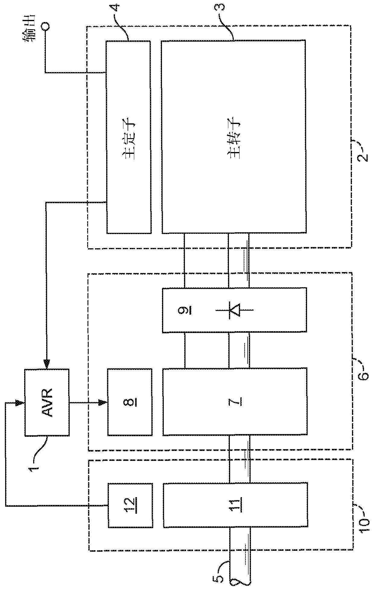
An excitation system and excitation technology, applied in the direction of magnetic circuit rotating parts, magnetic circuit shape/style/structure, synchronous motor for single-phase current, etc., can solve the problems of complex installation system, complex production, large rotating mass, etc. , to achieve the effect of reducing complexity, prolonging life and improving material consumption

Pending Publication Date: 2020-06-23
CUMMINS GENERATOR TECH LTD
View PDF6 Cites 0 Cited by
  • Summary
  • Abstract
  • Description
  • Claims
  • Application Information

AI Technical Summary

Problems solved by technology

However, it has been found that the production of the disclosed system is still rather complex and due to the number of rotating parts, the disclosed system requires a relatively complex installation system
In addition, the disclosed system has a relatively large rotating mass and may require the excitation system to be located outside the host housing

Method used


Image

  • Excitation system
  • Excitation system
  • Excitation system

Examples


Embodiment approach

[0145] Figure 19 Portions of an excitation system in another embodiment of the invention are shown. refer to Figure 19 , the excitation system includes the above reference Figure 2 to Figure 17 Combination exciter / PMG 100 of the form described. The combined exciter / PMG 100 includes an exciter stator 102 having stator windings 103 . The exciter stator 102 is mounted on a bracket 104 which may take the form of the bracket 76 described above. PMG stator (in Figure 19 not visible in ) is also mounted on bracket 104 , radially inward of combined exciter / PMG 100 . Figure 19 Also shown in is a rotor support 106 for supporting the combined exciter / PMG rotor core. As in the previous embodiments, a combined exciter / PMG rotor core is located between the exciter stator 102 and the PMG stator.

[0146] In this embodiment, the rotor support 106 takes the form of a rotor hub which is directly attached to the shaft 105 . Vent holes 108 are provided through the rotor hub 106 . Ve...


PUM


Abstract

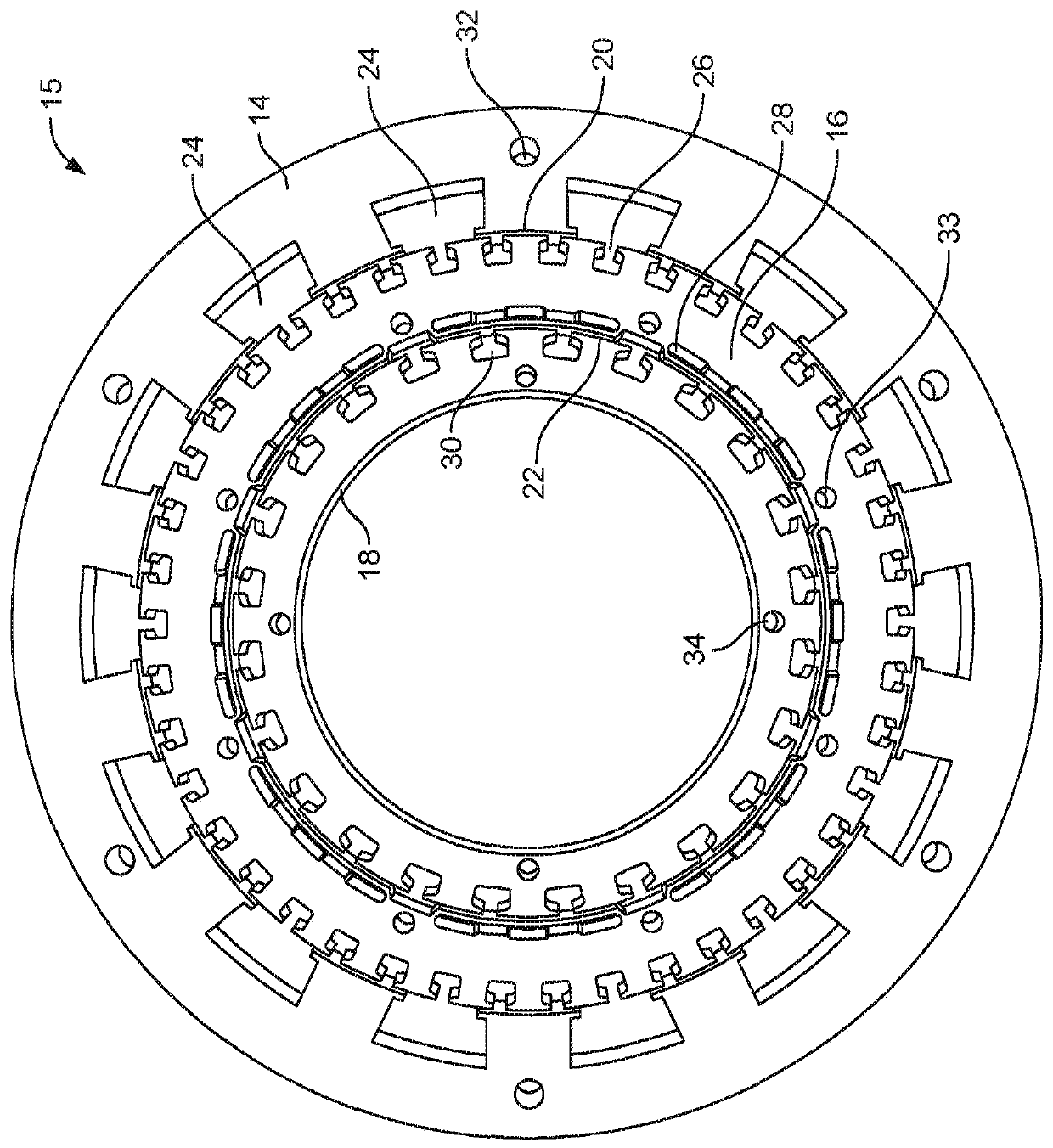
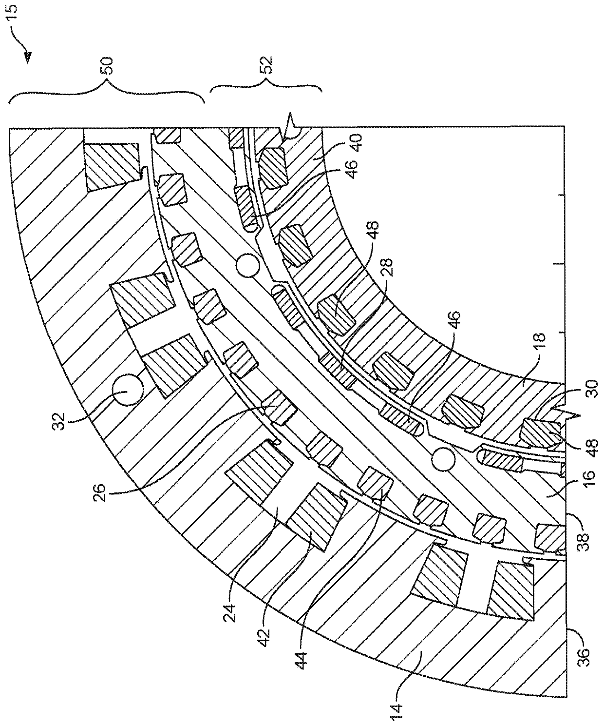
An excitation system (15) is disclosed for providing excitation to a main rotating electrical machine (2). The excitation system comprises an exciter (50) and an auxiliary generator (52). The exciterand the auxiliary generator have separate stator cores (14, 18) and share a common rotor core (16). The common rotor (16) core may be located between the two stator cores (14, 18). This may help to optimize space, improve material usage and reduce the total rotating mass. A mounting arrangement for the common rotor core is also disclosed.

Description

technical field [0001] This invention relates to an excitation system for providing excitation to a rotating electric machine, such as a synchronous generator. Background technique [0002] Synchronous generators operate by rotating the magnetic field generated by the rotor relative to the windings in the stator to produce an AC output in the stator windings. The magnetic field of the rotor is created by passing a DC current through the windings in the rotor. This DC current can be generated by an exciter mounted on the generator shaft. An automatic voltage regulator (AVR) may be provided to control the exciter and thereby the current supplied to the rotor windings. [0003] Power for the exciter can be derived from the output of the master (known as self-excitation). However, some applications may require the generator to have short circuit maintenance and / or enhanced overload capability. To achieve this, it is known to use a separate permanent magnet generator (PMG) mo...

Claims


Application Information

Patent Timeline
Patent Type & Authority Applications(China)
IPC IPC(8): H02K19/28H02K19/38H02K7/20H02K1/30H02K7/04H02K9/06H02K16/04H02K15/16
CPCH02K19/28H02K19/38H02K7/20H02K16/04H02K1/30H02K7/04H02K9/06H02K15/165H02K1/24H02K19/12
Inventor A·斯帕戈P·安帕拉韩
Owner CUMMINS GENERATOR TECH LTD
Learn More