
Vehicle side airbag device and manufacturing method of side airbag

Active Publication Date: 2016-04-28
TOYOTA JIDOSHA KK
View PDF9 Cites 27 Cited by
  • Summary
  • Abstract
  • Description
  • Claims
  • Application Information

AI Technical Summary

Benefits of technology

The present patent provides a vehicle side airbag device and a manufacturing method that can prevent an occupant from being affected by a rear bag section. The device is designed to inflate and deploy towards the vehicle front side of the side support section of the seatback. It has a front-rear left-right partitioning cloth that separates the rear bag section into left and right chambers, which inhibits inflation towards the vehicle rear side and reduces the impact on an occupant. Additionally, the front edge of the fabric is stitched together with the fabric of the bag body to reduce the number of stitching processes and the stitch length. Overall, this technology ensures the safety of all occupants in the vehicle during a side impact.

Problems solved by technology

Moreover, in the inflated and deployed state of the bag body, the tether provided to the at least one chamber out of the left and right chambers bears tension, such that inflation of the at least one chamber toward the vehicle front side is restricted.

Method used


Image

  • Vehicle side airbag device and manufacturing method of side airbag
  • Vehicle side airbag device and manufacturing method of side airbag
  • Vehicle side airbag device and manufacturing method of side airbag

Examples


first exemplary embodiment

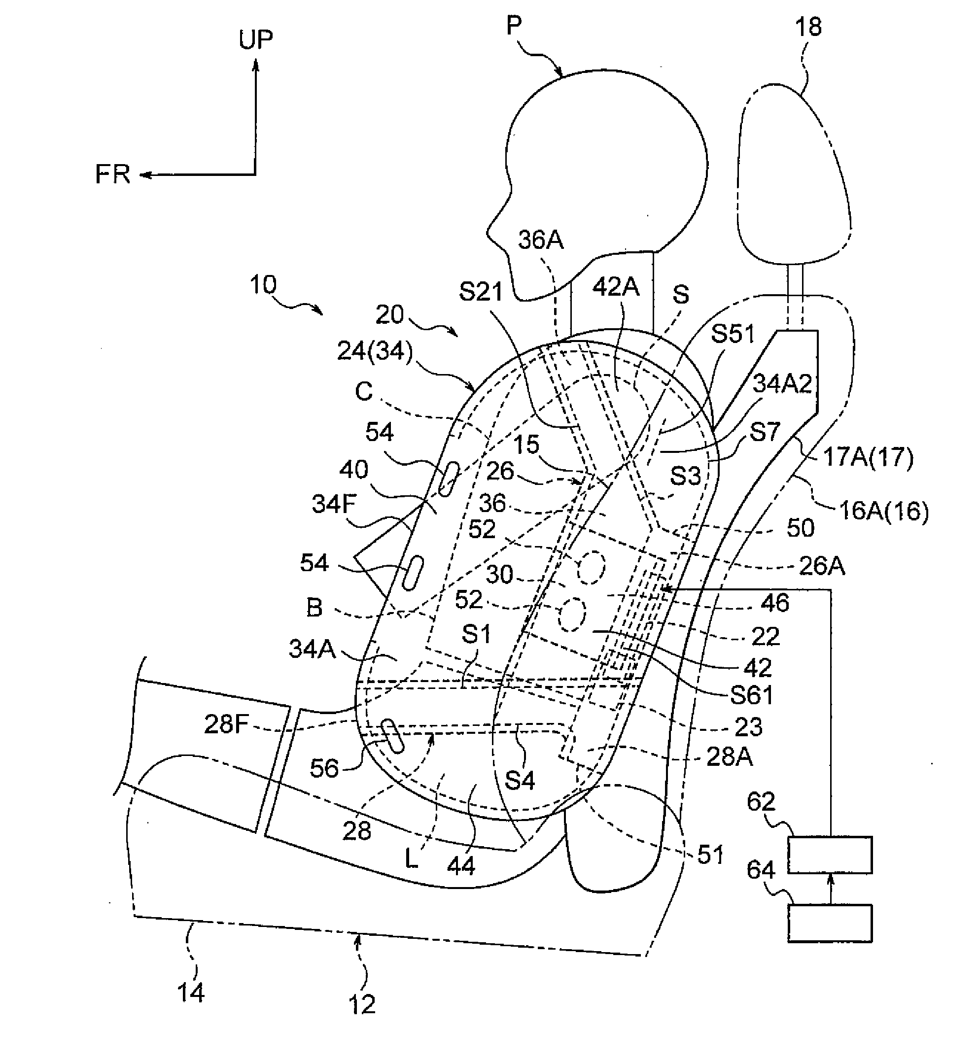
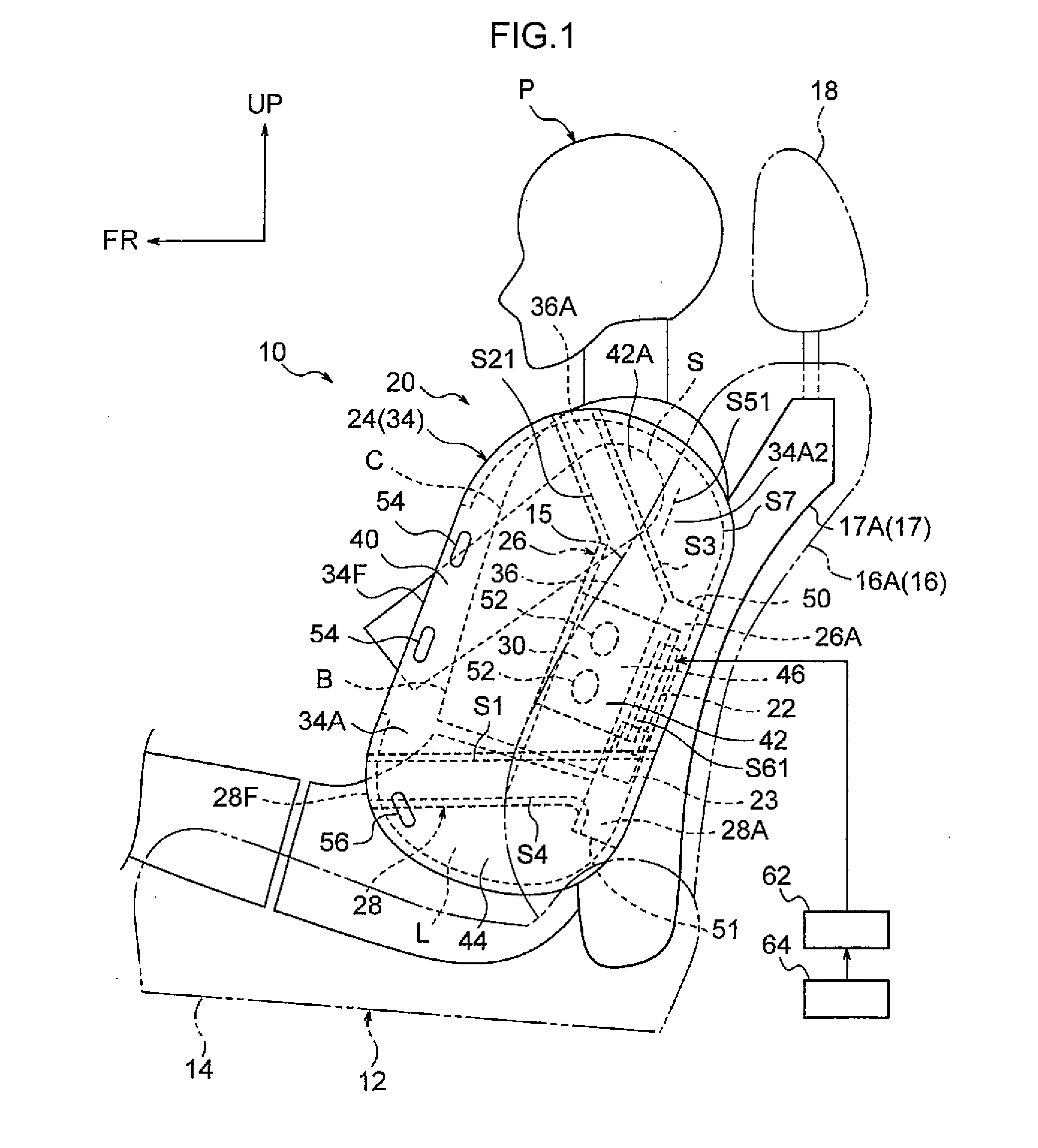
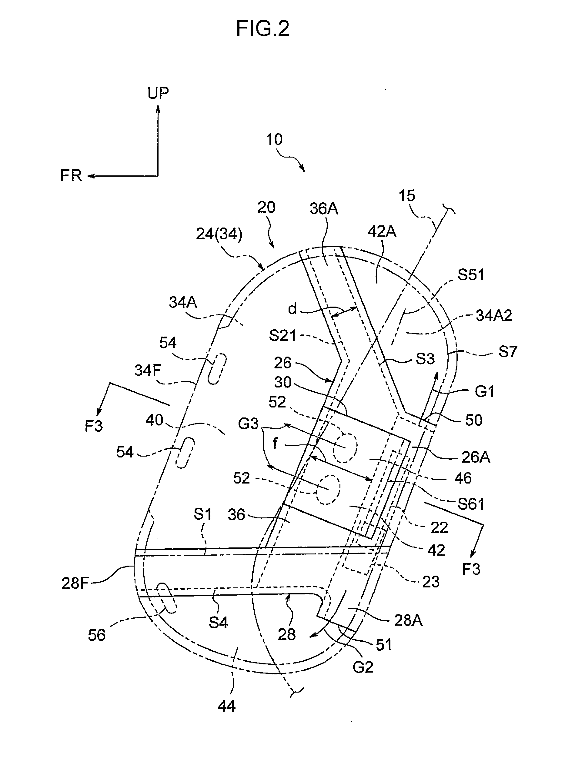
[0044]Explanation follows regarding a vehicle side airbag device 10 and a manufacturing method of a side airbag 20 according, to a first exemplary embodiment, based on FIG. 1 to FIG. 17. Note that in each of the drawings as appropriate, the arrow FR, the arrow UP, and the arrow OUT respectively indicate the front direction (the direction of travel), the tipper direction, and the outside in the vehicle width direction of a vehicle. In the following explanation, unless specifically stated otherwise, explanation using simply the front-rear, left-right, and up-down directions refers to the front-rear of the vehicle front-tear direction, the left-right of the vehicle left-right direction (vehicle width direction), and the up-down of the vehicle up-down direction.

[0045]A vehicle seat 12 illustrated in FIG. 1 is, for example, a driving seat in a left-hand drive automobile. The vehicle seat 12 includes a seat cushion 14 on which an occupant P sits, a seatback 16 that supports the back of th...

second exemplary embodiment

[0089]FIG. 19 is a side view corresponding to FIG. 2, illustrating an inflated and deployed state of a side airbag 82 provided to a vehicle side airbag device 80 according to a second exemplary embodiment of the present disclosure. FIG. 20 is an opened out plan view illustrating a state prior to stitching the side airbag 82 illustrated in FIG. 19.

[0090]In the side airbag 82, the up-down partitioning cloth 28 and the lower bag section 44 according to the first exemplary embodiment are omitted. In the side airbag 82, the front-rear left-right partitioning cloth 26 extends as far as the lower edge portion of the bag body 24, and a lower edge portion of the from-rear left-right partitioning cloth 26 is stitched to the lower edge portion of the base cloth 34 at the outer peripheral stitch portion S7. The left cloth 36 and the right cloth 38 of the front-rear left-right partitioning cloth 26 are formed with width dimensions that increase on progression from the upper edge portion side to ...


PUM


Abstract

The present disclosure provides a vehicle side airbag device including: a side airbag, housed inside a side support section of a vehicle seat, that inflates and deploys toward a vehicle front side upon being supplied with gas from an inflator, the side airbag including: a bag body that is formed in a bag shape; a front-rear left-right partitioning cloth that partitions the bag body into a front bag section and a rear bag section, and that partitions the rear bag section into a left and a right chamber in a row along a vehicle width direction in an inflated and deployed state of the bag body; and a tether, provided at at least one chamber of the left or the right chamber, that bears tension in the inflated and deployed state, and that restricts inflation of the at least one chamber toward the vehicle front side.

Description

CROSS-REFERENCE TO RELATED APPLICATION[0001]This application claims priority under 35 USC 119 from Japanese Patent Application No. 2014-218639, filed on Oct. 27, 2014, the disclosure of which is incorporated by reference herein.BACKGROUND[0002]1. Technical Field[0003]The present disclosure relates to a vehicle side airbag device and a manufacturing method of a side airbag.[0004]2. Related Art[0005]In a side airbag device described in Japanese Patent Application Laid-Open (JP-A) No. 2012-025182, a side airbag is sectioned into a first inflation section (rear bag section) and a second inflation section (front bag section) by a partitioning wall (front-rear partitioning section) provided at a position of the rib bones of an occupant in a suitable position. An inflator is provided inside the first inflation section, and gas generated by the inflator is supplied into the front bag section through a communication hole formed at the front-rear partitioning section. In the above case, by se...

Claims


Application Information

Patent Timeline
IPC IPC(8): B60R21/231B60R21/233D05B13/00B60R21/235D05B1/04D05B1/26B60R21/207B60R21/2338
CPCB60R21/23138B60R21/207B60R21/233B60R21/2338B60R21/235B60R2021/23576D05B1/26D05B13/00B60R2021/23146B60R2021/23324B60R2021/23382D05B1/04
Inventor FUJIWARA, YUSUKE
Owner TOYOTA JIDOSHA KK
Learn More