Pivoting ring seal

a ring seal and ring technology, applied in the field of medical procedures, can solve the problems of prolonging the time and risks of the procedure, increasing the cost of the procedure, injury or death of the patient, etc., and achieve the effect of preventing leakage or failure, increasing inflation and/or expansion

Active Publication Date: 2015-05-12
WL GORE & ASSOC INC
View PDF11 Cites 2 Cited by
  • Summary
  • Abstract
  • Description
  • Claims
  • Application Information

AI Technical Summary

Benefits of technology

[0007]Compared to traditional balloon seals requiring adhesives and / or crimped bands to prevent leakage or failure of an inflatable member, the ring seal of the invention (i.e. the ring of the invention, also sometimes referred to herein as band(s), ring member(s) and pivot ring(s)) offers a mechanical action which acts to tighten the seal with increasing inflation and / or expansion. As the inflatable member increases in size, one side of the ring is lifted and pivots around a fulcrum between the ends of the ring seal causing the opposite side of the ring seal to decrease in diameter and / or exert a compressive force. The pivoting (and the reduction in diameter) causes the opposite part of the seal to tighten about an inner member allowing for a higher-pressure seal. In addition to a higher pressure seal, the working length of the inflatable member can be adjusted by moving the ring seal along the length of the inflatable member while it is not inflated.
[0010]Another embodiment of the invention comprises a medical device comprising an inflatable member having opposing ends, a smaller deflated profile and a larger inflated profile, a working length, and a ring member having opposing ends, said ring member being slidable, whether in situ or prior to insertion of a device in the body, or some combination, to any position between the opposing ends of the deflated inflatable member, wherein when one opposing end of said ring member increases in diameter, the other opposing end of said ring member decreases in diameter upon inflation of the inflatable member. In one embodiment, the inflatable member drives the increase in the diameter of the ring member in one opposing end. In another embodiment, the decrease in diameter of one opposing end of said ring member restricts inflation of a portion of said inflatable member.
[0011]In another embodiment, said inflatable member is disposed over an elongate member. In another embodiment, said elongate member is a catheter or a guidewire. In another embodiment, the decrease in diameter of the opposing end of said ring member makes said end constrict about said inflatable member and / or said elongate member. In another embodiment, the constriction of the opposing end of said ring member against said inflatable member and / or said elongate member results in a seal of at least one end of said inflatable member. In another embodiment, as the diameter of an opposing end of said ring member decreases, it further constricts against said inflatable member and / or said elongate member resulting in a tighter seal of at least one end of said inflatable member. In another embodiment, the decrease in diameter of one of the opposing ends of said ring member restricts axial movement of said ring member. In another embodiment, said inflatable member is a medical balloon. In another embodiment, said medical balloon comprises expanded polytetrafluoroethylene (ePTFE). In another embodiment, the position of said ring member adjusts the working length of said medical balloon. In another embodiment, one method of adjusting the position of the ring member is by sliding the ring member along the axis of said medical balloon to the appropriate location in said inflatable member. In another embodiment, said medical balloon further comprises a balloon cover. In another embodiment, said balloon cover comprises ePTFE. In another embodiment, said medical balloon comprises a drug coating on said balloon and / or balloon cover. In another embodiment, said ring member comprises a resilient metal. In another embodiment, said resilient metal is nitinol. In another embodiment, the position of said ring member adjusts the working length of the expandable portion of said inflatable member.

Problems solved by technology

This extends the time and risks of the procedure.
Changing balloons, however, is a costly, time-consuming and potentially risky procedure that could lead to injury or death of the patient.

Method used


Image

  • Pivoting ring seal
  • Pivoting ring seal
  • Pivoting ring seal

Examples


example 1

Constructing Pivot Ring

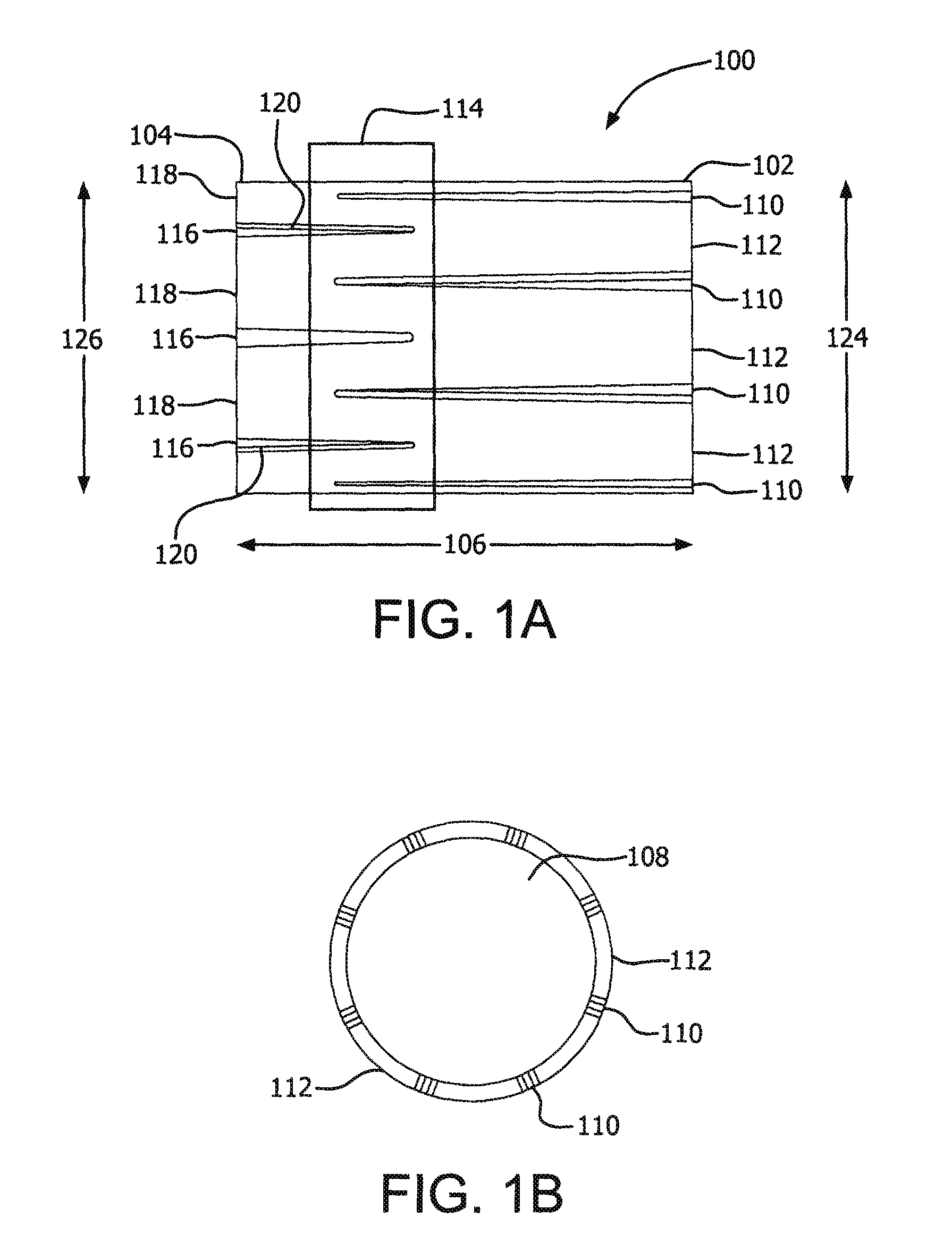
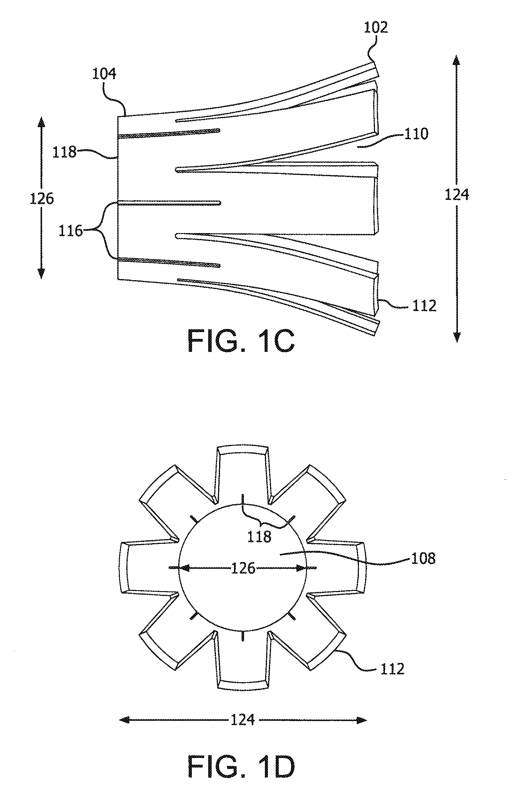
[0075]A pivot ring was made by cutting the pattern illustrated in FIG. 5 into a nitinol tube with an outside diameter of 0.086″ and inside diameter of 0.074″. For ease of illustration, FIG. 5 depicts the flat pattern that was cut into the tube. The cut pattern provided for 8 slots in clamping side 504 of the ring with widths of 0.004″ each. Fully closed, this would result in roughly a 0.064″ diameter or a 0.010″ reduction in inside diameter. The cut utilized a staggered orientation of opening slits 502 and clamping slots with roughly a 2:1 length ratio (opening finger length:closing finger length). FIG. 5B is shown as tubular depiction of the resulting band.

example 2

Constructing a Balloon Catheter

[0076]EPTFE balloon construct was made according to the teachings of U.S. Pat. No. 6,923,827, Campbell, et al. Forty layers of ePTFE were wrapped around a 6 mm mandrel at a high angle and in opposing directions. This tube was heated at 380° C. for approximately 8 minutes to fuse the layers together. The tube was removed from the mandrel and stretched which resulted in a reduction in inside diameter to at least below 0.075″. The tubing was then slid onto a 0.075″ stainless steel mandrel. A sacrificial overwrap of ePTFE film was placed over the tubing and its length was evenly reduced to 60% of its original length. The tube was heated at 380° C. for one minute and the sacrificial ePTFE was removed. This ePTFE tube was dipped into a 12% solution of Biospan polyurethane (DSM, Netherlands) in DMAC (N,N Dimethylacetamide). Three dips were made into the solution with a heat / drying step between each step to dry off the solvent. This tube was removed from the m...

example 3

Illustration of Pivot Ring on a Balloon Catheter

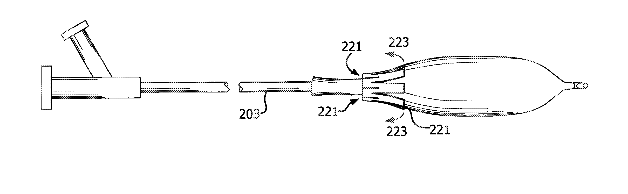
[0078]The catheter construct of Example 2 was inflated to 6 atm's with the band in a location approximately 28 mm from the proximal seal (FIG. 6A). This resulted in a total inflated length of roughly 28 mm and no inflation media was observed passing underneath the pivoting ring member. The balloon was deflated (FIG. 6B) and the ring was repositioned distally about 10 mm (as depicted by arrow 615 in FIG. 6C). The balloon was reinflated to 8 atm's and the new inflated length of the balloon was about 38 mm (FIG. 6D) and again, no inflation media was observed passing underneath the pivoting ring. A closer image of the pivot band in its pivoted state (FIG. 7, with reference numbers as described in FIG. 1) is shown to demonstrate the band embedding into the balloon construct to make a seal and prevent axial migration upon inflation.


PUM


Abstract

The instant invention provides for a pivoting ring that can be used as a seal for an inflatable member. The pivoting ring seal offers a mechanical action which acts to tighten with increasing inflation and / or expansion of an inflatable member. As the inflatable member increases in pressure and / or size, one side of the ring is lifted and pivots around a fulcrum in the middle of the ring seal causing the opposite side of the ring seal to decrease in diameter. The pivot ring causes the opposite part of the seal to tighten about an inner member allowing for a higher-pressure seal. In addition to a higher pressure seal, the working length of the inflatable member can be adjusted by moving the ring along the length of the inflatable member.

Description

CROSS-REFERENCE TO RELATED APPLICATIONS[0001]This application claims the priority benefit under 35 U.S.C. 119(e) of U.S. Provisional Application No. 61 / 475,822 filed on Apr. 15, 2011 which is incorporated by reference herein in its entirety.BACKGROUND OF THE INVENTION[0002]There are many medical procedures which employ balloon catheters. In most cases, the length of the balloon must be pre-determined by the clinician prior to selection and insertion of the balloon catheter into the body. For example, in balloon angioplasty, the length of the diseased blood vessel is first determined. Usually, the physician determines in advance the approximate size of the vessel area to be treated. This can be done, for example, through fluoroscopic X-ray, ultrasound imaging, and / or CAT scanning techniques. When balloon length choices are few, a clinician will generally choose a length shorter than the length of the lesion to be treated and will sequentially dilate different portions of the vessel. ...

Claims


Application Information

Patent Timeline
Patent Type & Authority Patents(United States)
IPC IPC(8): A61M29/00A61F2/958A61M25/10
CPCA61M25/10A61M25/1018A61M2025/1068A61M2025/1084A61F2210/0061A61F2250/0067A61F2250/0069A61F2/958A61F2210/0014A61M25/104A61M29/02A61M2205/0216A61F2/82
Inventor CAMPBELL, CAREY V.FRIEDMAN, NATHAN L.TRAPP, BENJAMIN M.
Owner WL GORE & ASSOC INC
Why Eureka
Try Eureka