If the connection is too weak, it may leak.
Because the types of solvents that are sometimes used as the mobile phase are often toxic and because it is often expensive to obtain and / or prepare many samples for use, any such connection failure is a serious concern.
Moreover, the time involved in disconnecting and then connecting a column (or other component) is unproductive because the LC system is not in use and the operator is engaged in plumbing the system instead of preparing samples or other more productive activities.
Hence, the replacement of a column in a conventional LC system involves a great deal of wasted time and inefficiencies.
More recently, however, it has been realized that the use of stainless steel components in a LC system have potential drawbacks in situations involving biological samples.
This presents problems because the
detector's measurements (and thus the chromatogram) of a given sample may not accurately reflect the sample if some of the sample's components or ions remain in the tubing, and do not pass the
detector.
Perhaps of even greater concern, however, is the fact that ions from the stainless steel tubing may detach from the tubing and flow past the
detector, thus leading to potentially erroneous results.
Additionally, ions can easily bind to biological compounds of interest, resulting in changes to the molecules that affect their
retention time in the column.
One reason for this is that a valve having a large volume will contain a relatively large volume of liquid, and when a sample is injected into the valve the sample will be diluted, decreasing the resolution and sensitivity of the analytical method.
A
stationary phase particle as small as 1 micron is common; the resulting high column packing density leads to substantially increased
system pressure at the head of the column.
However, for some types of analyses (e.g.,
biological testing and
metal /
ion analysis), stainless steel or other metals are not desired in the fluid path as the
metal could interfere with the testing.
Such small inside diameters are typically not available in stainless steel or other
high pressure tubing.
The types of fluidic connection systems between the tubes that carry fluids and the ports that receive fluids in these high-pressure applications are limited.
These types of connections sometimes may have drawbacks, however.
For example, the size of cone-shaped fittings and threaded fittings are dependent on the type and size of any given port, which makes quickly interchanging a tube fitted with a particular cone or threaded fitting between various ports difficult.
However, ferrules and lock rings can become deformed after multiple uses (e.g., by connecting, disconnecting, and reconnecting to various ports).
Connection assemblies which attempt to effectuate a seal for high-pressure applications can require a significant amount of torque to effectuate a fluid-tight seal, making the creation of such seals difficult without the use of additional tools and increasing the risk of damage to the fitting
assembly or its components due to overtightening.
Moreover, experience suggests that many users do not like to use various tools to connect or disconnect tubing from components such as those in various
AI systems.
It is believed that users often apply different amounts of torque to connect or disconnect tubing and the components in such systems, thus resulting in potential problems caused by over-tightening or under-tightening (e.g., leakage or loss of sealing when the fluid is under pressure).
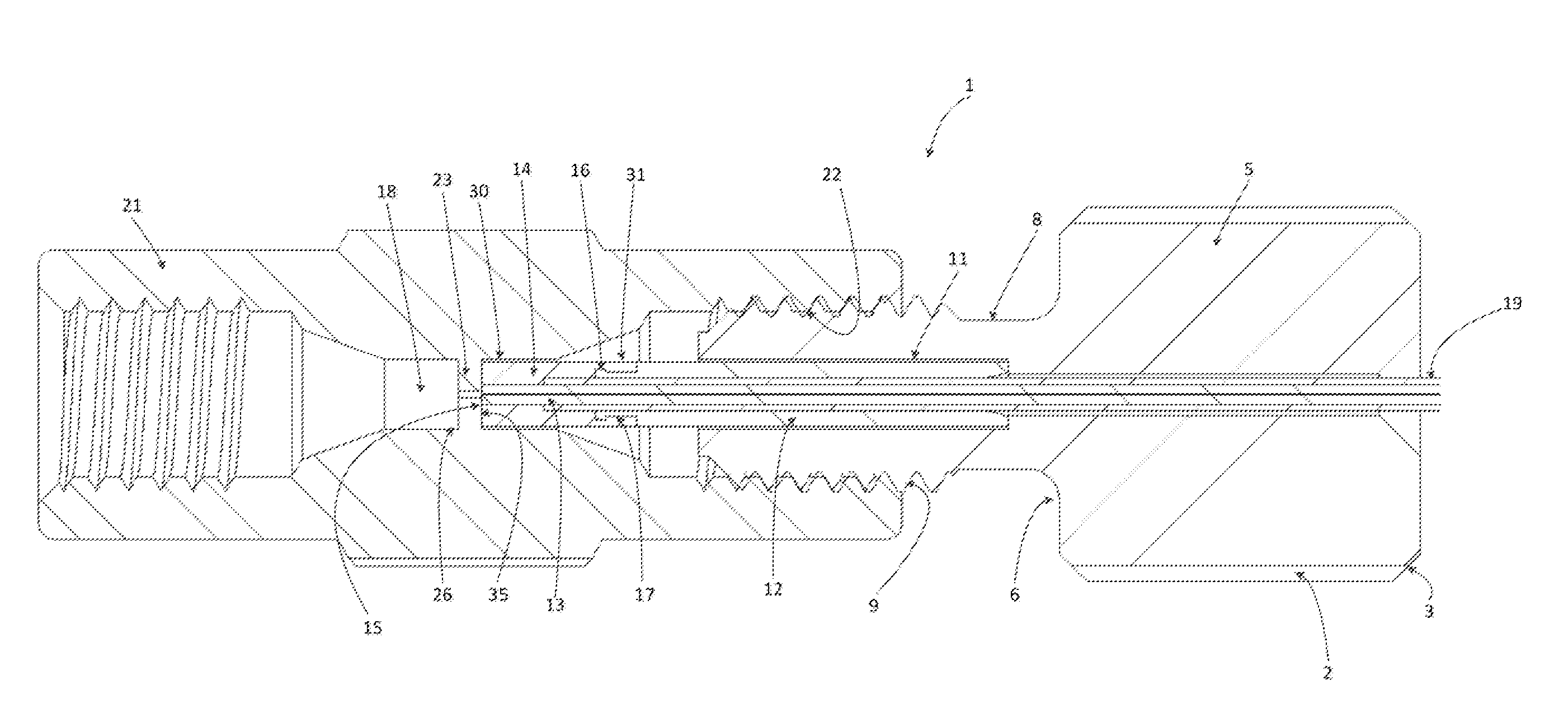
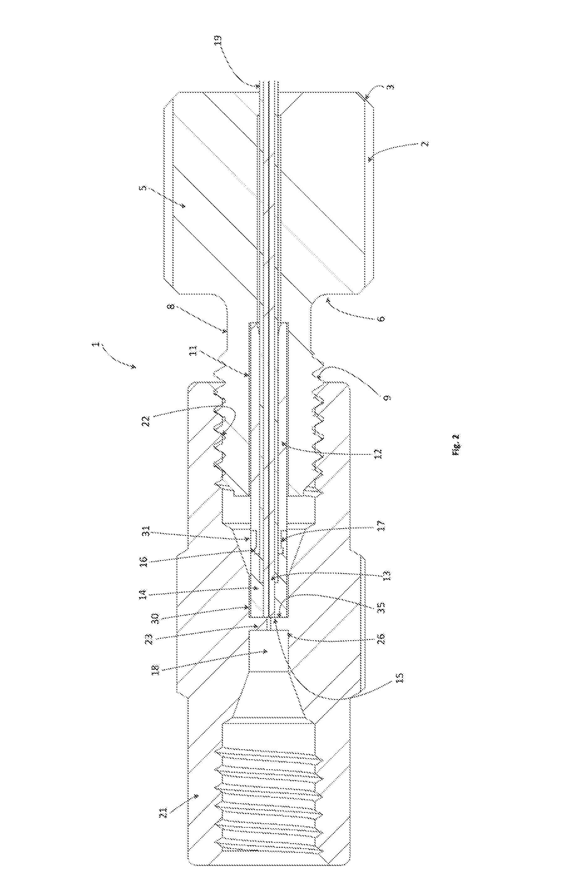
The tube is typically forced into the bottom of the coned port, but there is not currently a mechanism to ensure there is not a gap or space at the port bottom.
The space at the bottom of the port is a concern for those performing liquid chromatography experiments due to the potential to negatively influence the results with carry over and band broadening.
Carry over can produce very unstable results for obvious reasons.
Band broadening is when the peaks identifying a substance become less symmetric and make identification more difficult when peaks of different molecules have similar retention times.
One issue with conventional ferrules used with coned ports is that the torque required to deform / deflect is typically above finger tight levels in order to achieve UHPLC pressures (e.g., above 12,000 psi or so).
End-face seals at such
high pressure may require smooth surfaces, however.

