Bearing shoe for supporting a rotor journal in a turbine engine

a technology of rotor journals and bearings, which is applied in the direction of sliding contact bearings, engine components, mechanical apparatus, etc., can solve the problems of increasing the coefficient of friction, affecting the stability of the rotor, and requiring a large amount of breakaway torque for large shafts, so as to reduce the force needed

Active Publication Date: 2018-12-25
SIEMENS ENERGY GLOBAL GMBH & CO KG
View PDF18 Cites 0 Cited by
  • Summary
  • Abstract
  • Description
  • Claims
  • Application Information

AI Technical Summary

Benefits of technology

[0005]In at least one embodiment, the rotor journal support system may include one or more aligning rings forming at least a portion of a cylindrical opening through which a rotor journal may extend. The rotor journal support system may include one or more first retaining plates extending radially inward further than a radially inward surface of the aligning ring. The second retaining plate may extend radially inward further than the radially inward surface of the aligning ring. The second retaining plate may be offset axially from the first retaining plate. The rotor journal support system may include one or more bearing shoes positioned radially inward from the inward surface of the aligning ring. The rotor journal support system may include one or more bearing shoe supports extending from the bearing shoe radially outward to the aligning ring. The bearing shoe support may include an outer bearing surface having at least a partial spherical shape configured to bear against a radially inward surface of the aligning ring. The partial spherical shaped outer bearing surface enables relatively unconfined movement of the bearing shoe.
[0006]Movement of the bearing shoe may be limited in a circumferential direction by one or more shoe support pin recesses on an outer side surface of the bearing shoe support and at least one shoe support pin positioned within the shoe support pin recess and extending into the aligning ring. In another embodiment, the shoe support pin may prevent movement of the bearing shoe in a circumferential direction with one or more shoe support pins extending from the at least one aligning ring toward the at least one bearing shoe. The shoe support pin may include a mating surface configured to mate with a mating surface of the at least one bearing shoe support. In another embodiment, the outer bearing surface of the bearing shoe support may extend radially outward into a spherical cavity within the aligning ring. The rotor journal support system may include one or more lift oil feed systems in fluid communication with the spherical cavity within the aligning ring. The lift oil feed system may also include one or more outlets in fluid communication with a radially inner surface of the bearing shoe.
[0014]An advantage of the rotor support system is that the system enables a bearing shoe to have a degree of misalignment between the rotor journal and the bearing shoe while preventing misalignment of the bearing shoe while a rotor journal is installed.
[0015]Another advantage of the rotor support system is that the system enables the bearing shoe support enables the bearing shoe to be moved in any direction other than circumferentially in one direction downward and radially outward.
[0016]Still another advantage of the rotor support system is that the movement of the bearing shoe may be limited in a circumferential direction by one or more shoe support pin recesses on an outer side surface of the bearing shoe support and one or more shoe support pins positioned within the shoe support pin recess and extending into the aligning ring.
[0017]Another advantage of the rotor support system is that the system limits rotation of one or more bearing shoes about an axis orthogonal to a longitudinal axis of a rotor journal and orthogonal to a pivot axis of the bearing shoe during installation of a rotor journal to keep the bearing shoe properly aligned with the rotor journal such that the torque needed to begin rotating the rotor journal from a stationary position is minimal.

Problems solved by technology

Large scale shafts often require use of a tremendous amount of breakaway torque to begin to rotate the shafts.
The mechanisms that are used to keep the pads in the desired location during handing and installation often inhibit pads from properly aligning with the rotor.
If the pad is not properly aligned to the shaft, contact at the outer edges will significantly increase the coefficient of friction and result in a much larger breakaway torque.
This situation creates a low pressure zone that allows for the high pressure lift oil to leak out of the bearing without providing the proper lifting force to the rotor.
The thinner oil film will potentially allow for more of the pad to come into contact with the rotor and result in a significantly higher breakaway torque.

Method used


Image

  • Bearing shoe for supporting a rotor journal in a turbine engine
  • Bearing shoe for supporting a rotor journal in a turbine engine
  • Bearing shoe for supporting a rotor journal in a turbine engine

Examples


Embodiment Construction

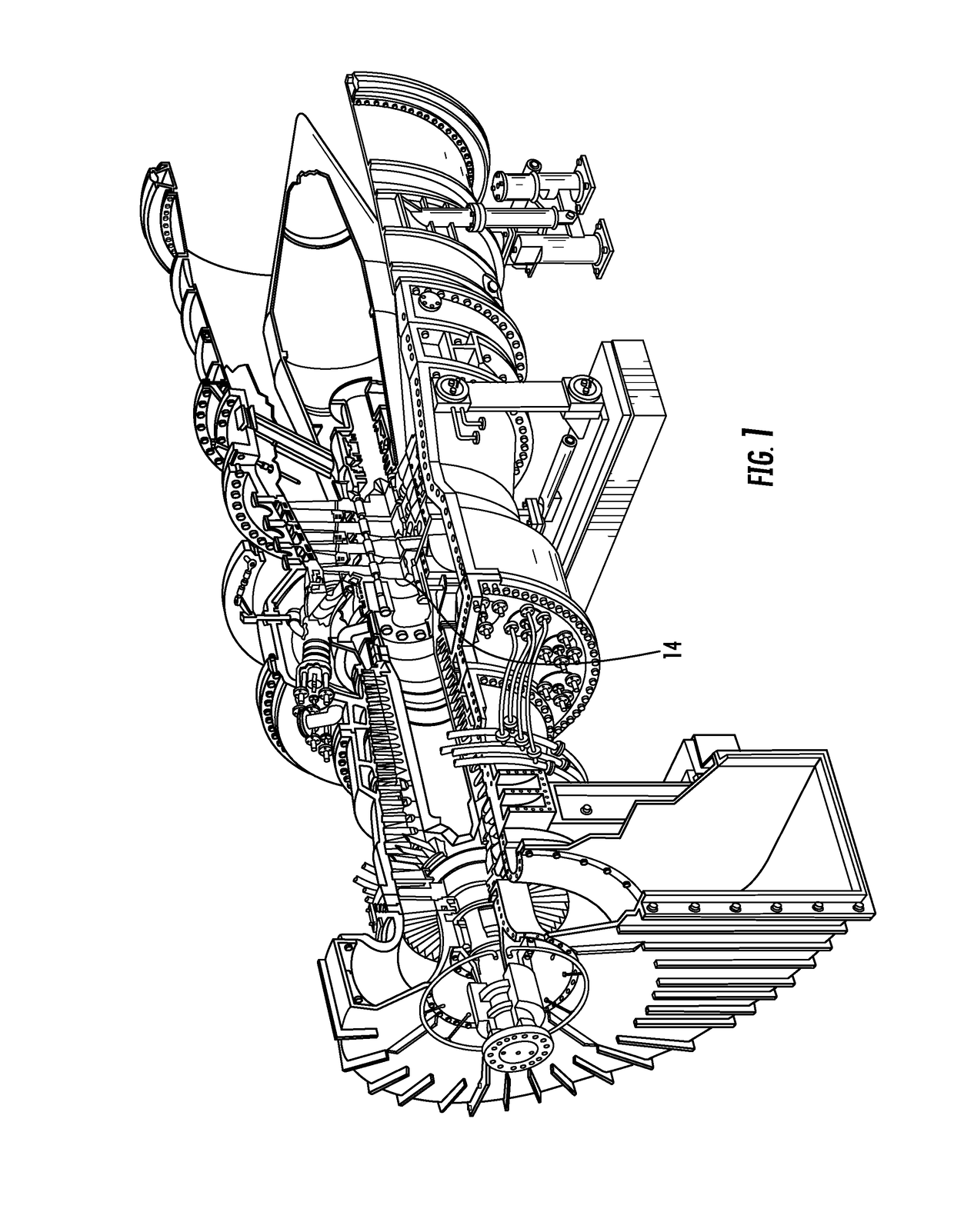
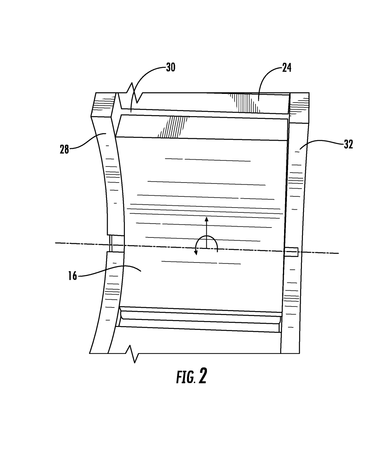
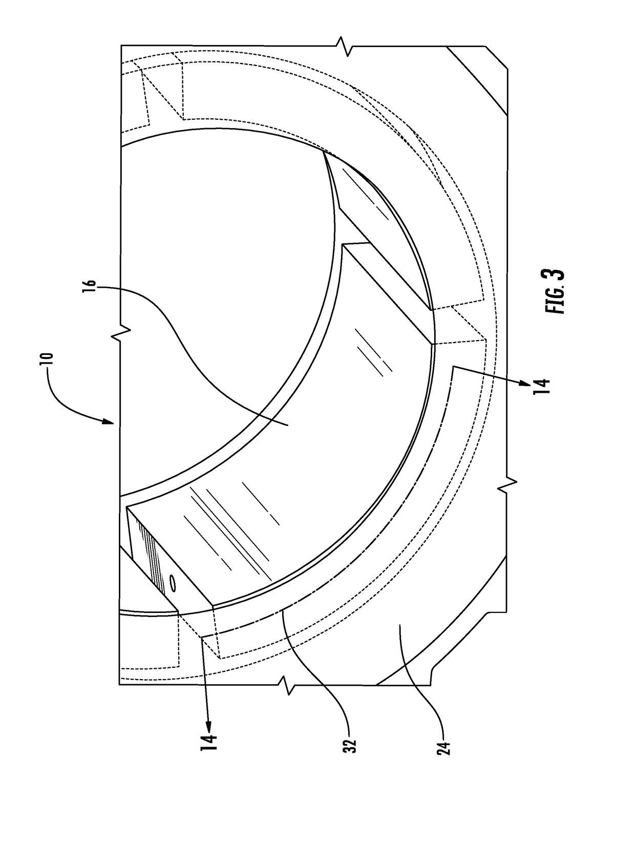
[0039]As shown in FIGS. 1-19, a rotor journal support system 10 configured to allow for a bearing shoe 16 to properly align to a rotor 14 while keeping the bearing shoe 16 constrained during handling, installation, and operation limit is disclosed. The rotor journal support system 10 may be configured to enable limited movement of a bearing shoe 16 such that when the rotor journal 14 is installed and rests upon the bearing shoe 16, the bearing shoe 16 is properly aligned with the rotor journal 14, thereby resulting in reduced force needed to turn the rotor journal 14 from a stop than when the bearing shoe 14 is misaligned. In particular, the rotor journal support system 10, in part, may include a number of embodiments permitting greater movement of the bearing shoe 16 than conventional systems. The rotor journal support system 10 may include one or more bearing shoe supports 88 extending radially outward from the bearing shoe 16. The bearing shoe support 88 may include an outer bear...


PUM


Abstract

A rotor journal support system (10) configured to allow for a bearing shoe (16) to properly align to the rotor (14) while keeping the bearing shoe (16) constrained during handling, installation, and operation limit is disclosed. The rotor journal support system (10) may be configured to enable limited movement of a bearing shoe (16) such that when the rotor journal (14) is installed, the bearing shoe (16) is properly aligned with the rotor journal (14), thereby requiring less torque to turn the rotor journal (14) from a stop than when the bearing shoe (16) is misaligned. The rotor journal support system (10) may include bearing shoe supports (88) extending radially outward from the bearing shoe (16). The bearing shoe support (88) may include an outer bearing surface (100) having at least a partial spherical shape configured to bear against the aligning ring (24). In this position, the bearing shoe support (88) enables the bearing shoe (16) to be moved in any direction other than circumferentially and radially outward.

Description

[0001]This application claims priority to PCT Application No. PCT / US2015 / 013724 filed Jan. 30, 2015, the contents of which are incorporated herein by reference.FIELD OF THE INVENTION[0002]This invention is directed generally to support systems for rotor journals and, more particularly, to support systems for rotor journals in turbine engines.BACKGROUND[0003]Large scale shafts often require use of a tremendous amount of breakaway torque to begin to rotate the shafts. The rotors overcome friction at breakaway and during rotation. To reduce the breakaway torque and subsequent motor size, high pressure lift oil applications are used. The rotor journals are often supported by a plurality of bearing shoes. One of the reasons for use of tilt-pad journal bearings is the larger misalignment tolerance between the rotor and bearing. To allow for this misalignment capability, the pads must be free to rotate and tilt to properly align the rotor. At the same time, the pads must be retained in the...

Claims


Application Information

Patent Timeline
Patent Type & Authority Patents(United States)
IPC IPC(8): F16C17/03F16C41/04F16C43/02F16C33/10
CPCF16C17/03F16C33/1045F16C43/02F16C41/04F16C2360/23
Inventor FARABOW, III, JOHN WILLIAMMYERS, GERALD A.CURTIN, WILLIAM J.KURSCH, MICHAELSCHULZ, LOTHAR K.
Owner SIEMENS ENERGY GLOBAL GMBH & CO KG
Why Eureka
Try Eureka