Duct tie rod and method

Pending Publication Date: 2022-10-27
H J FISCHER
View PDF0 Cites 0 Cited by
  • Summary
  • Abstract
  • Description
  • Claims
  • Application Information

AI Technical Summary

Problems solved by technology

In this latter regard, such features should not be sufficiently weakened that contemplated air pressures exerted against the duct wall will b

Method used


Image

  • Duct tie rod and method
  • Duct tie rod and method
  • Duct tie rod and method

Examples


Embodiment Construction

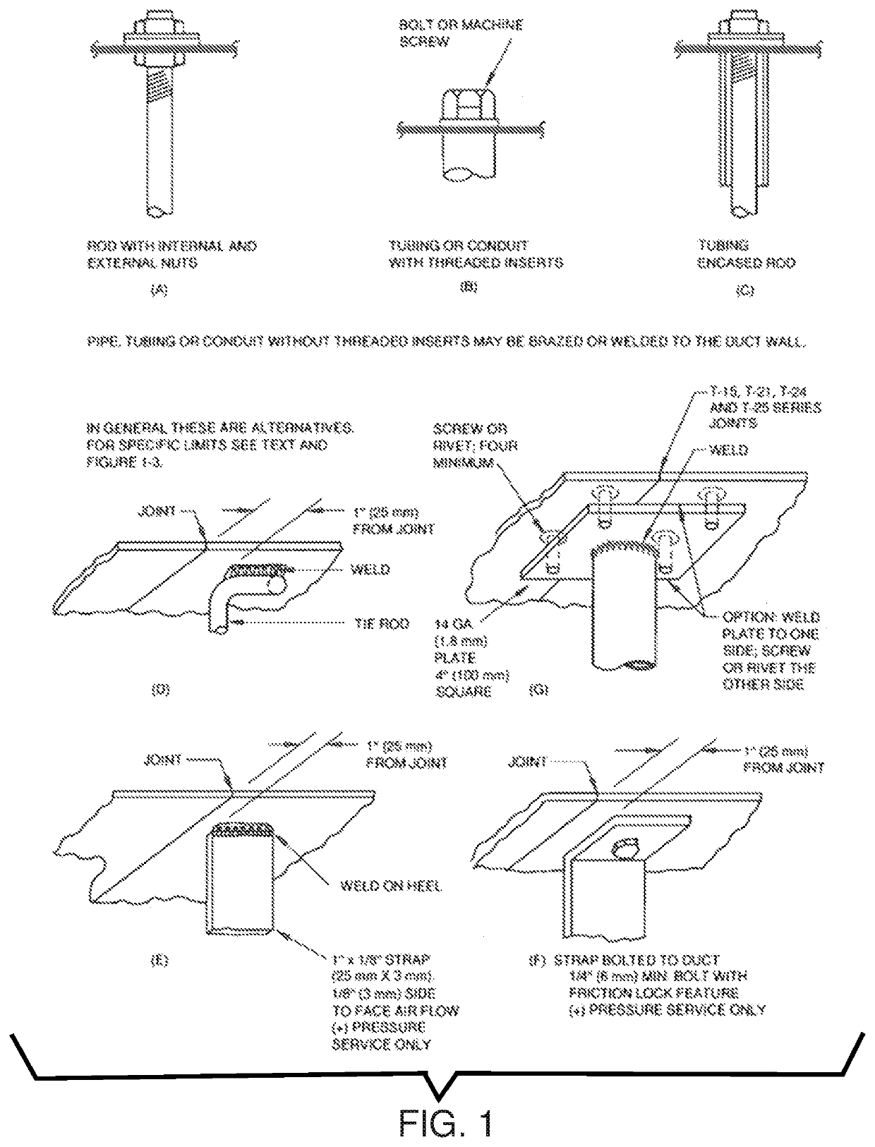
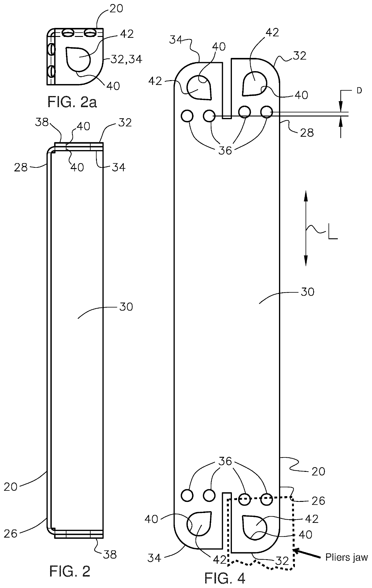
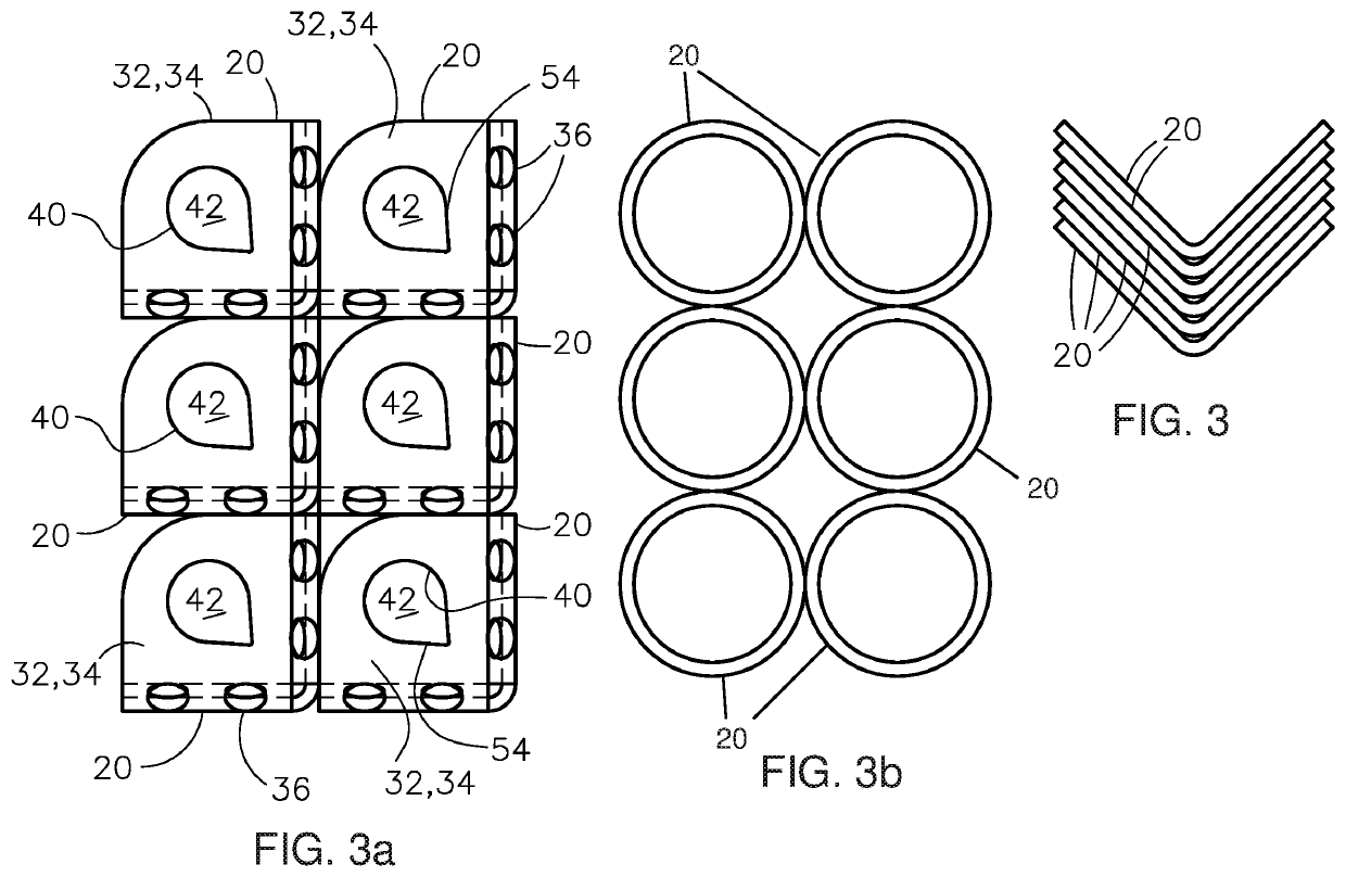
[0063]Referring to FIGS. 1-20 of the drawings, wherein like numbers refer to like parts, several embodiments of a tie rod the invention are shown. Referring particularly to FIGS. 2-5k, a basic configuration of a tie rod 20 of the invention is shown, along with several optional hole configurations for receiving a fastener for attaching to a duct wall 22, that can be provided in a ready to use configuration, see FIGS. 2 and 2a, or a stackable shipping and storage configuration, see FIGS. 3, 3a, 3b, and 4. The tie rods 20 of the invention can be simply and inexpensively fabricated from sheet metal or other suitable material, including automatically, and are securely fastenable quickly and easily to duct walls 22, see FIGS. 7, 8, 9, 12-20, optionally by one person, without need of tightening nuts and bolts together from inside and outside of the duct 24, although that is an option, see FIG. 17. Optionally, the tie rod 20 can be fabricated in one of several straight, nestable configurati...


PUM


Abstract

A tie rod for spanning a duct interior to join duct walls bounding the duct interior, that can be simply and inexpensively fabricated from sheet metal or other suitable material, including automatically, securely fastenable quickly and easily to the duct walls, often by one person, and which can be configured to be nestable for efficient storage and shipping, of elongate construction for spanning a duct interior, with a transverse attachment flange or flanges that can be pre-bent or bent onsite at the installation location via special bending features to snug to a duct wall, and include holes for threadedly receiving fasteners, having a shape and size to reduce fastening torque, with a two attachment flange configuration that resiliently self retains the fastener against loosening from vibration and other forces.

Description

[0001]This application claims the benefit of U.S. Provisional Application No. 63 / 178,189, filed Apr. 22, 2021.TECHNICAL FIELD[0002]This invention relates generally to a tie rod for spanning a duct interior to join duct walls bounding the duct interior, and, more particularly, that can simply and inexpensively fabricated from sheet metal or other suitable material, including automatically, is securely fastenable quickly and easily to the duct walls, often by one person, and which can be configured to be nestable for efficient storage and shipping.BACKGROUND ART[0003]U.S. Provisional Application No. 63 / 178,189, filed Apr. 22, 2021, is incorporated herein by reference in its entirety.[0004]The use of tie rods to reinforce and prevent or reduce deflection of duct walls in the HVAC (Heating, Ventilating, and Air Conditioning) industry are required as well as desired at certain locations within a duct system. Essentially, during operation, when air is flowing through the duct interior, po...

Claims


Application Information

Patent Timeline
IPC IPC(8): F24F13/02F16B37/04
CPCF24F13/0209F16B37/042F16B5/02F16B25/0021F16B25/106F16B43/001F16B5/0225
Inventor FISCHER, JOSHUAFISCHER, HERBERT J.
Owner H J FISCHER
Why Eureka
Try Eureka