Lens and lighting device

a technology for lighting devices and lenses, applied in lighting and heating apparatus, semiconductor devices for light sources, instruments, etc., can solve the problems of affecting the appearance of lighting devices, ssl elements have a much lower luminous output, and become increasingly difficult to meet the world's energy needs as well as to control carbon, so as to achieve high-directional light output

Active Publication Date: 2016-05-19
SIGNIFY HLDG BV
View PDF5 Cites 25 Cited by
  • Summary
  • Abstract
  • Description
  • Claims
  • Application Information

AI Technical Summary

Benefits of technology

[0009]The present invention seeks to provide a lens that can be used to generate highly directional light outputs in compact lighting devices.

Problems solved by technology

With a continuously growing population, it is becoming increasingly difficult to meet the world's energy needs as well as to control carbon emissions to kerb greenhouse gas emissions that are considered responsible for global warming phenomena.
Indeed, in many jurisdictions the production and retailing of incandescent light bulbs has been outlawed, thus forcing consumers to buy energy-efficient alternatives, e.g. when replacing incandescent light bulbs.
A drawback of SSL element-based lighting devices is that individual SSL elements have a much lower luminous output than e.g. incandescent, tungsten halogen or fluorescent light bulbs, such that it is necessary to include multiple SSL elements in a single lighting device such as a light bulb to obtain the required luminous output levels.
However, this is generally perceived to negatively affect the appearance of the lighting device, which hampers the market penetration of such lighting devices, although recently the emergence of so-called chip-on-board (COB) SSL elements, e.g. COB LEDs, in which multiple SSL chips are packaged together as one lighting module such that in use the luminous surface of the lighting device gives the appearance of a single lighting panel, have addressed this problem to a large extent.
Another problem hampering the penetration of the consumer markets by such lighting devices is that it is far from trivial to control the shape of the light output of such devices, at least in a cost-effective manner.
This is a particular problem when a highly directional light output is required, e.g. a light bulb having a small beam angle, e.g. a beam angle of less than 30°.
In many small lighting devices such as compact light bulbs, there is insufficient space to accommodate optical elements such as the aforementioned prior art Fresnel lens.

Method used


Image

  • Lens and lighting device
  • Lens and lighting device
  • Lens and lighting device

Examples


Embodiment Construction

[0032]It should be understood that the Figures are merely schematic and are not drawn to scale. It should also be understood that the same reference numerals are used throughout the Figures to indicate the same or similar parts.

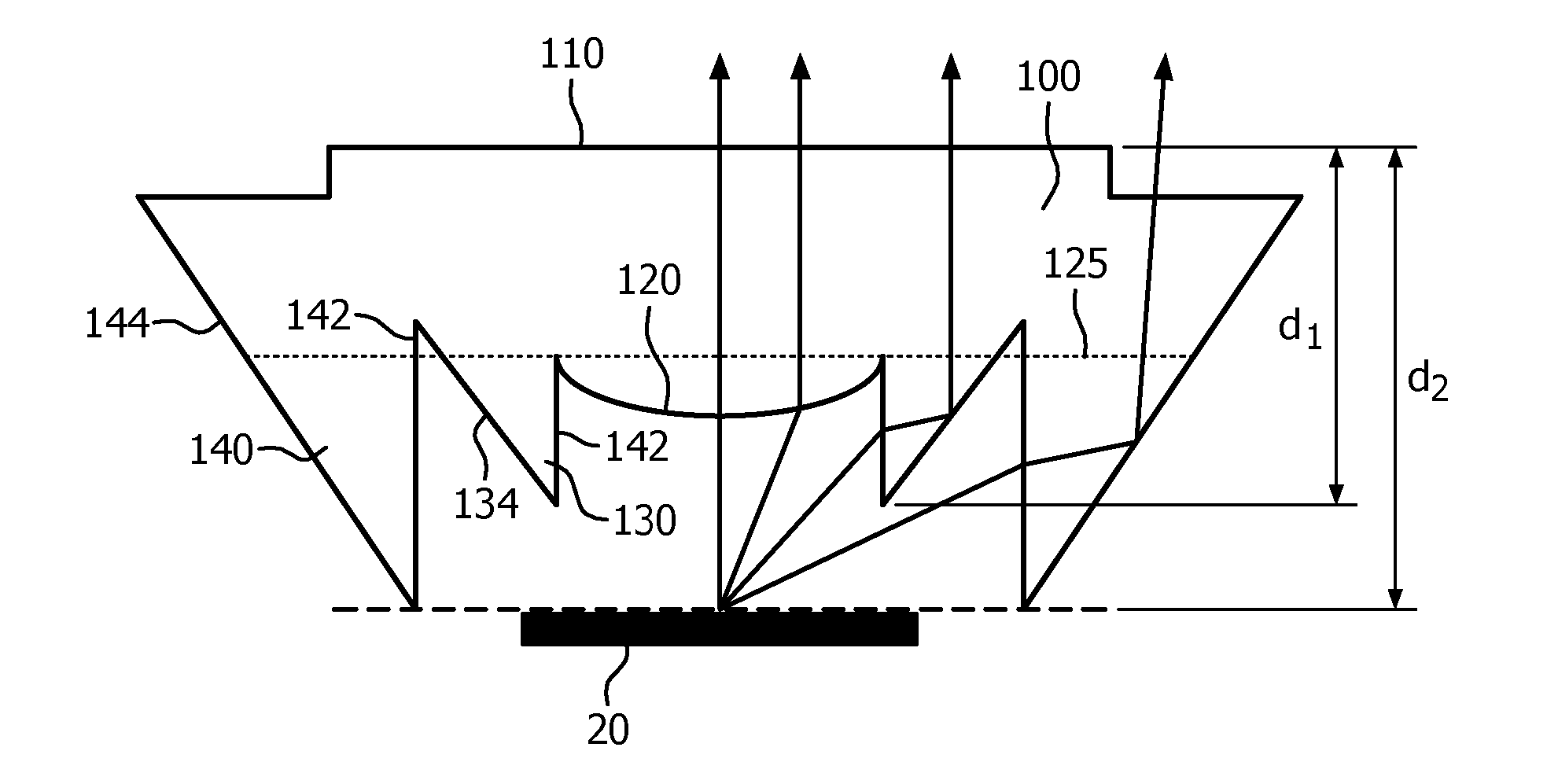
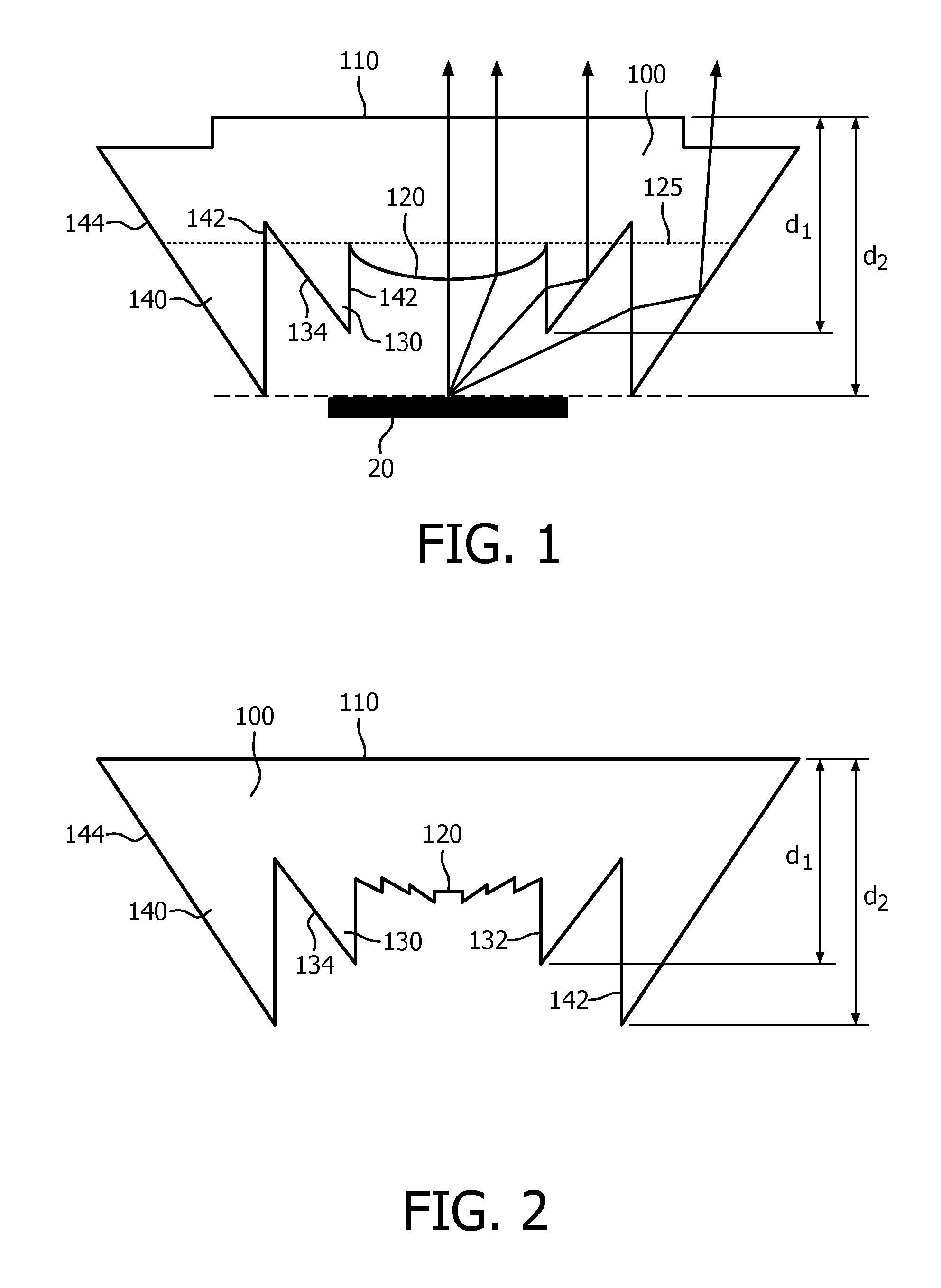
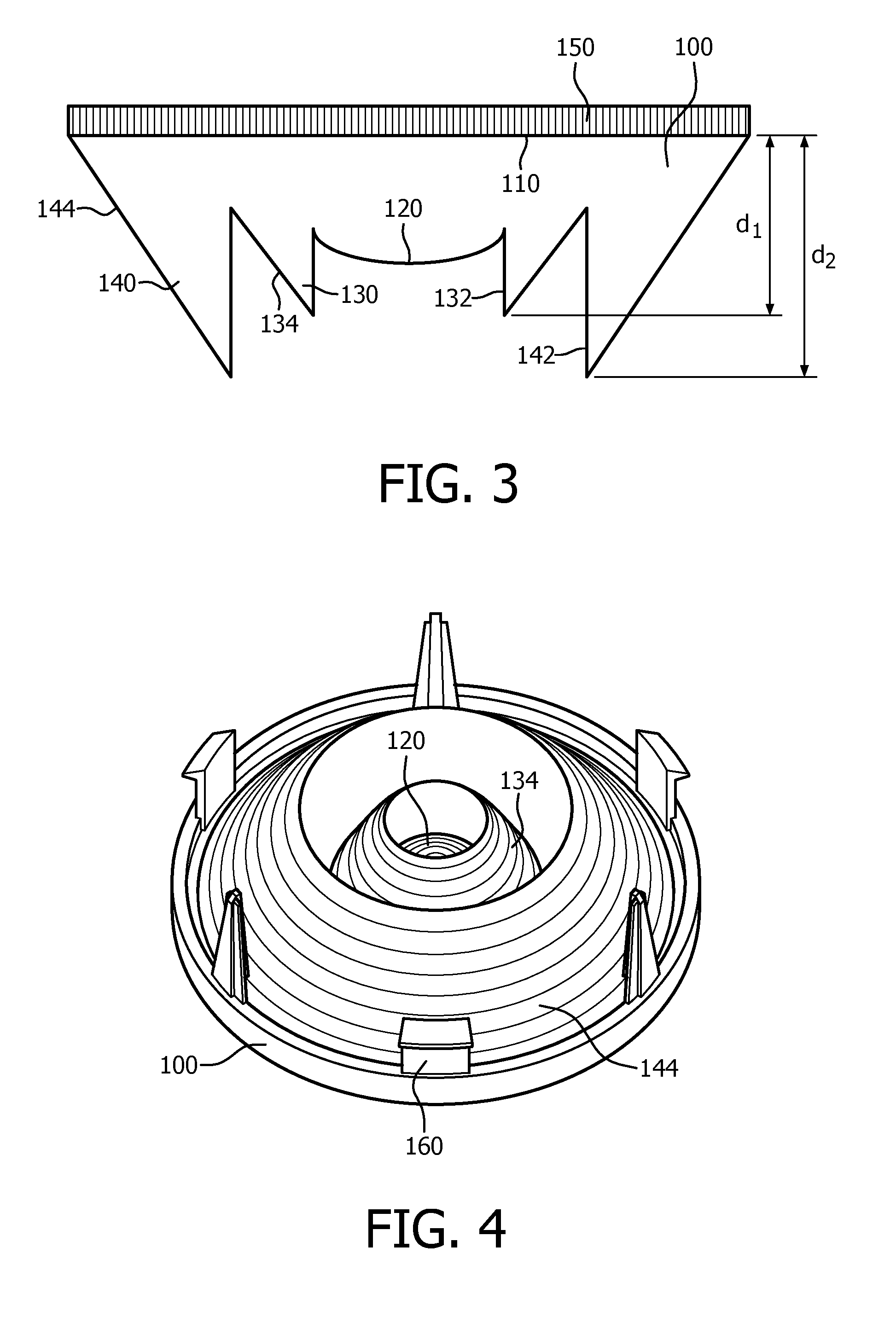
[0033]FIG. 1 schematically depicts a lens 100 according to an embodiment of the present invention. The lens 100 comprises a light entry surface defined by a central lens portion 120, an inner annular reflective element 130 and an outer annular reflective element 140 defining the side surface of the lens 100. The lens 100 further comprises a light exit surface 110 opposite the light entry surface. In use, the light entry surface of the lens 100 typically faces a light source such as a surface comprising one or more solid state lighting (SSL) elements 20 such as light emitting diodes. In an embodiment, the inner annular reflective element 130 and the outer annular reflective element 140 are directly adjacent to each other, i.e. the lens 100 comprises no more th...


PUM


Abstract

Disclosed is a lens (100) for a lighting device (10) comprising a solid state lighting element (20), the lens comprising a light exit surface (110); a central lens portion (120) opposite said light exit surface; an inner annular reflective element (130) opposite said light exit surface and extending away from said light exit surface by a first distance (d1), said inner annular reflective element delimiting said central lens portion; and a side surface defined by an outer annular reflective element (140) opposite said light exit surface and extending away from said light exit surface by a second distance (d2) that is larger than the first distance such that the outer annular reflective element extends beyond the inner annular reflective element. A lighting device such as a light bulb including such as lens is also disclosed.

Description

FIELD OF THE INVENTION[0001]The present invention relates to a lens for a lighting device comprising a solid state lighting element.[0002]The present invention further relates to a lighting device comprising such a lens.BACKGROUND OF THE INVENTION[0003]With a continuously growing population, it is becoming increasingly difficult to meet the world's energy needs as well as to control carbon emissions to kerb greenhouse gas emissions that are considered responsible for global warming phenomena. These concerns have triggered a drive towards more efficient electricity use in an attempt to reduce energy consumption.[0004]One such area of concern is lighting applications, either in domestic or commercial settings. There is a clear trend towards the replacement of traditional incandescent light bulbs, which are notoriously energy inefficient, with more energy efficient replacements. Indeed, in many jurisdictions the production and retailing of incandescent light bulbs has been outlawed, th...

Claims


Application Information

Patent Timeline
Patent Type & Authority Applications(United States)
IPC IPC(8): F21V5/04F21K99/00F21V5/00
CPCF21V5/045F21K9/137F21V5/004F21K9/233F21V17/164G02B3/08G02B19/0028G02B19/0061
Inventor SHEN, MOLI, YUNZOU, AIBIN
Owner SIGNIFY HLDG BV
Why Eureka
Try Eureka