Removable compact hinge and method of use

a compact, hinge technology, applied in the direction of hinges, wing accessories, manufacturing tools, etc., can solve the problems of difficult repositioning accuracy, permanent holes in wood, and functional hardware replacement and repositioning,

Active Publication Date: 2016-05-26
HARDWARE RESOURCES
View PDF25 Cites 2 Cited by
  • Summary
  • Abstract
  • Description
  • Claims
  • Application Information

AI Technical Summary

Benefits of technology

[0008]An adjustment plate connected between the hinge arm and the base of the attachment mechanism cooperates with a vertical adjustment cam, a lateral adjustment screw, and a horizontal adjustment cam to provide adjustability of the removable compact hinge in three directions. The vertical adjustment cam connects the hinge arm and the adjustment plate to the attachment mechanism and provides vertical movement of the hinge arm relative to the attachment mechanism. The lateral adjustment screw connects the hinge arm to the adjustment plate and provides lateral movement of the hinge arm relative to the adjustment plate. The horizontal adjustment cam connects the hinge arm to the adjustment plate and provides horizontal movement of the hinge arm relative to the adjustment plate.

Problems solved by technology

Wood screws leave permanent holes in the wood and are very difficult to reposition accurately.
In many situations, such as refacing kitchen cabinets, functional hardware must be replaced and repositioned which the permanent holes make difficult.

Method used


Image

  • Removable compact hinge and method of use
  • Removable compact hinge and method of use
  • Removable compact hinge and method of use

Examples


Embodiment Construction

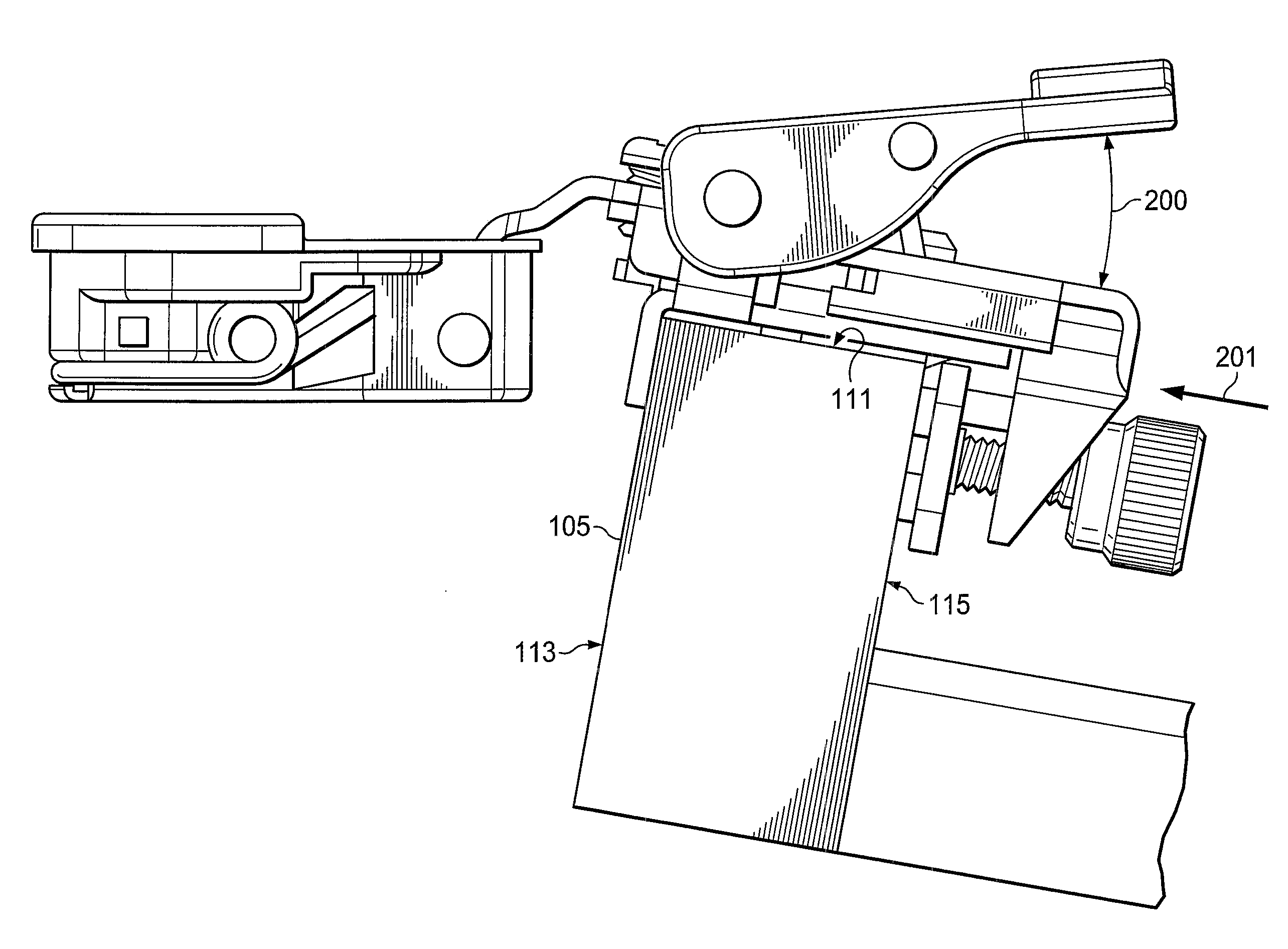
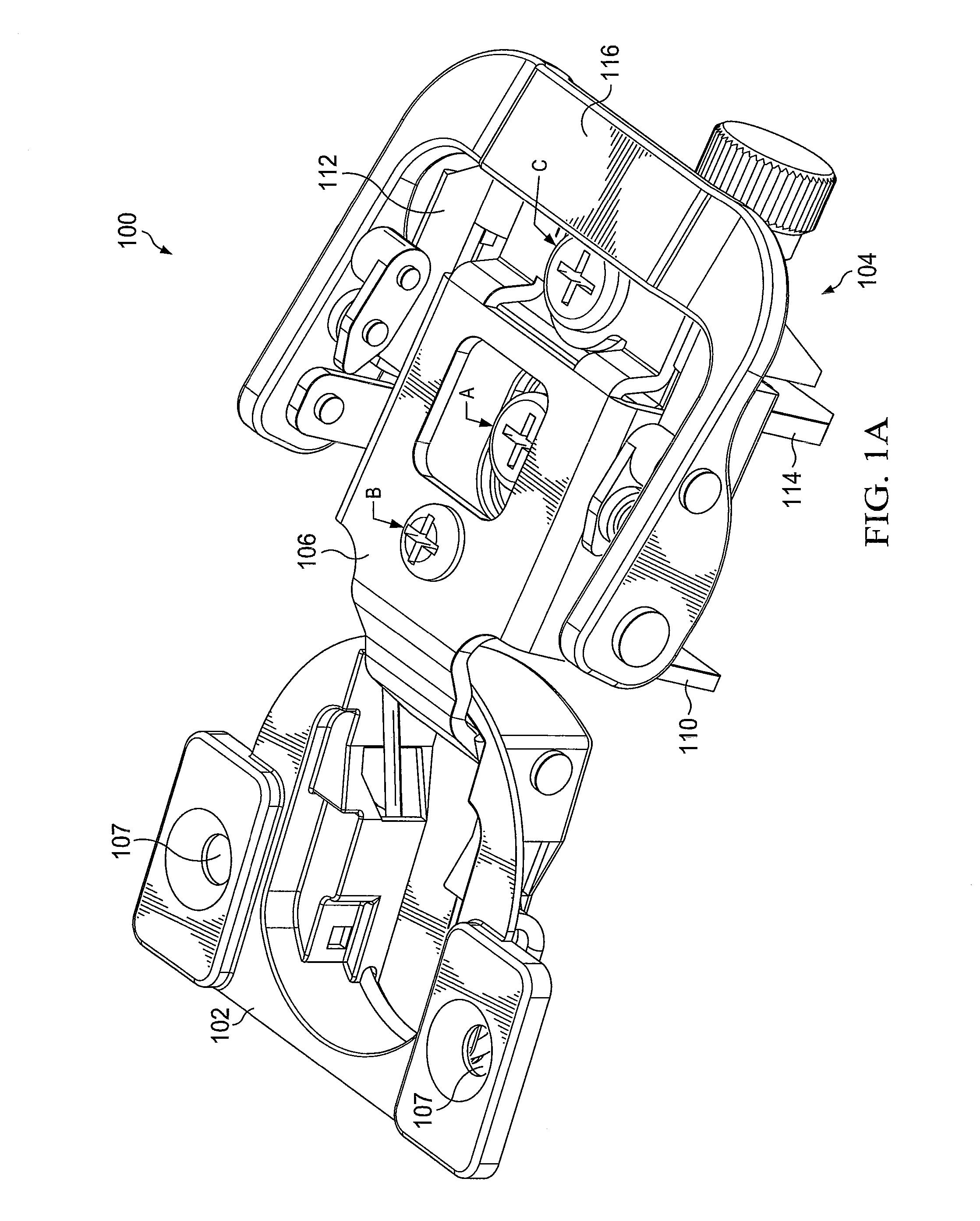
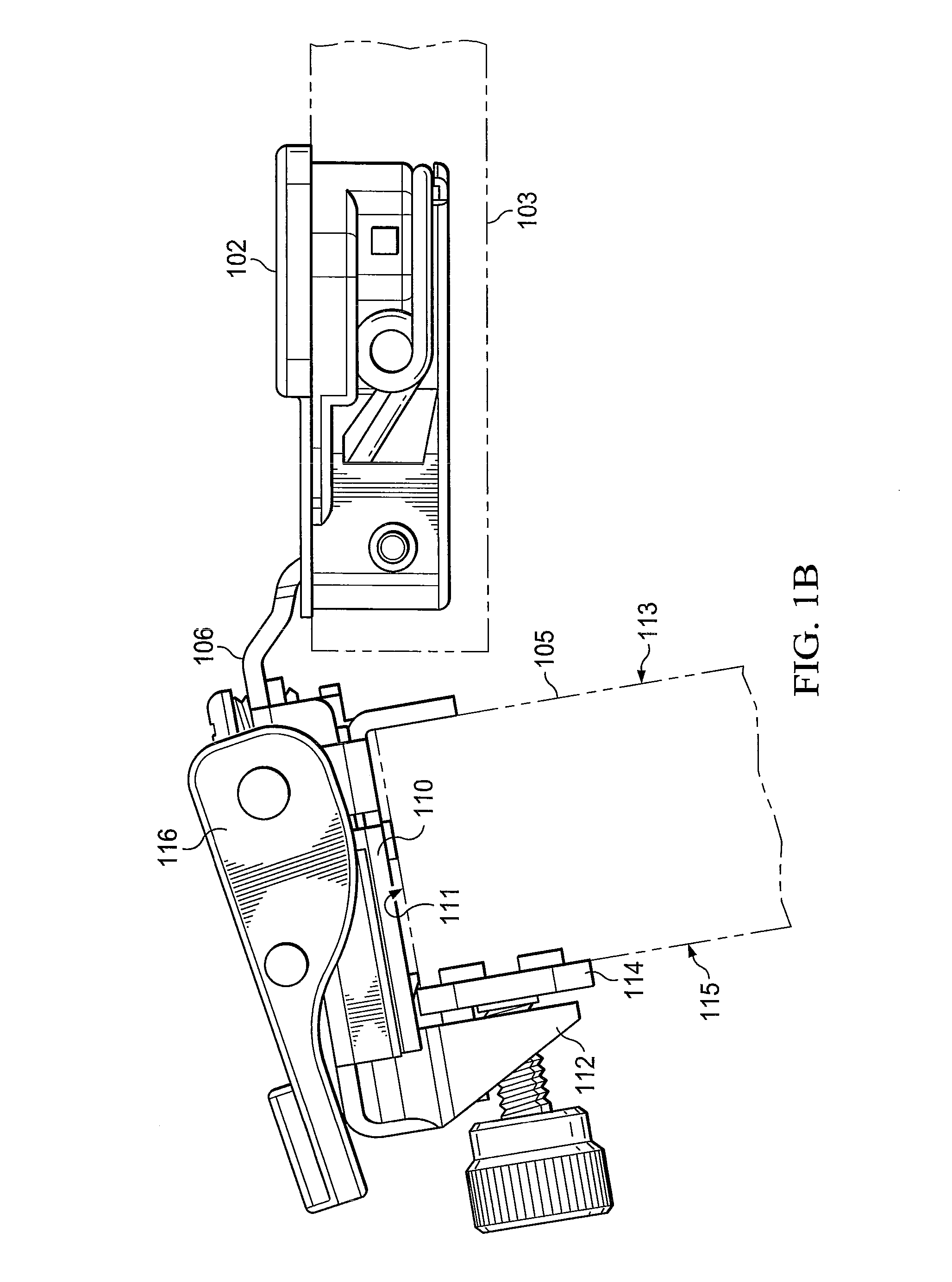
[0026]Referring to FIGS. 1A, 1B and 2A, removable hinge 100 comprises hinge cup 102 pivotally connected to attachment mechanism 104 by hinge arm 106. Typically, hinge cup 102 is affixed to cabinet door 103 with screws through mounting holes 107. Attachment mechanism 104 is removably attached to cabinet carcass 105 as will be described below. Removable hinge 100 is repositionable between a “locked” position to cabinet carcass 105 and an “unlocked” position. In the locked position, the attachment mechanism is securely affixed to the cabinet carcass. In the unlocked position, the attachment mechanism can be removed from attachment to the cabinet carcass. In a preferred embodiment, the components of removable hinge 100 are typically constructed of metal such as cast aluminum or steel alloy plate stock.

[0027]Attachment mechanism 104 comprises base 110, dog 112, pressure plate 114, lever 116, and opposing links 118 and 119. Base 110 is attached to cabinet carcass 105 at faces 111 and 113....


PUM

PropertyMeasurementUnit
compressive forceaaaaaaaaaa
pressureaaaaaaaaaa
vertical movementaaaaaaaaaa

Abstract

Disclosed is a removable compact hinge for pivotal connection between a furniture piece and a door. The apparatus incorporates a clamping attachment mechanism in order to avoid permanent mounting holes and to provide quick installation and adjustable installation location. The apparatus comprises a hinge cup pivotally connected to an attachment mechanism ion with a hinge arm. The attachment mechanism comprises a base slidably engaged with a sliding body, the sliding body including an adjustable pressure plate. A lever works with a set of links to slide the sliding body with respect to the base towards the furniture piece and mechanically and releasably clamp the attachment mechanism to the furniture piece without the use of typical wood screws thereby preserving the integrity of the furniture piece. The apparatus further includes adjustability in the vertical, horizontal, and lateral directions.

Description

CROSS-REFERENCE TO RELATED APPLICATIONS[0001]This application claims the benefit of U.S. Provisional Patent Application No. 62 / 082,500 filed on Nov. 20, 2014, the contents of which are incorporated herein by reference.FIELD OF THE DISCLOSURE[0002]The present disclosure relates to hinge mechanisms for connecting a cabinet door to a cabinet carcass. In particular, the disclosure relates to a removable compact hinge capable of quick installation and repositioning without the need for typical connection hardware.BACKGROUND OF THE DISCLOSURE[0003]In the typical hinged connection between a cabinet door and a cabinet carcass, a hinge mechanism will include a hinge cup pivotally connected to a hinge body by a hinge arm. A common configuration positions the hinge cup in a custom bore in the cabinet door. The hinge body is mounted to the cabinet carcass either directly or through the use of a mounting plate. Mounting screws are typically used to mount the hinge cup to the door and the hinge b...

Claims


Application Information

Patent Timeline
Patent Type & Authority Applications(United States)
IPC IPC(8): E05D7/12F16B2/12E05D5/06F16B2/18
CPCE05D7/125E05D5/065F16B2/12F16B2/185E05D5/08E05D7/0415E05D7/123E05Y2600/502E05Y2600/51E05Y2600/626E05Y2800/178E05Y2900/20F16B2/18
Inventor LAIRD, RACHELMCELVEEN, TRAVISMCGREGOR, DENNIS
Owner HARDWARE RESOURCES
Why Eureka
Try Eureka