Eureka AIR delivers breakthrough ideas for toughest innovation challenges, trusted by R&D personnel around the world.

LED end of life optical comparator and methods for determining LED light fixture end of life

Active Publication Date: 2016-06-02
ASTRONICS
View PDF3 Cites 2 Cited by
  • Summary
  • Abstract
  • Description
  • Claims
  • Application Information

AI Technical Summary

Benefits of technology

This patent is about ways to determine when a light fixture is reaching the end of its lifespan. It uses a control LED that is briefly turned on to measure its output. This LED is compared with an illumination LED that is always on. By measuring the difference in output between the two, the level of deterioration of the illumination LED can be determined. If the output drops below a certain threshold, an alarm may be sounded. This invention helps to prolong the lifespan of light fixtures and reduce maintenance costs.

Problems solved by technology

However, over the long lifespan of a typical LED, its light output will degrade in an manner that is difficult or impossible to predict, rather than simply “burning out”—as was the case with previous, incandescent bulb and flashtube lights.
Due to this unpredictable degradation, aircraft lighting manufacturers have had difficulty providing a way to determine when a light fixture no longer meets the FAA specifications and needs replacement (the “end of life” or “EOL” of the fixture).
However, if the light output of the fixture has dropped significantly below the specified value before the predetermine number of hours, then the fixture may be operating past its end of life.
Conversely, if the light output is still significantly above the specified value at the predetermined number of hours, then the end of life determination may be premature.
However, the use of software complicates aircraft-related certification.

Method used


Image

  • LED end of life optical comparator and methods for determining LED light fixture end of life
  • LED end of life optical comparator and methods for determining LED light fixture end of life
  • LED end of life optical comparator and methods for determining LED light fixture end of life

Examples


Embodiment Construction

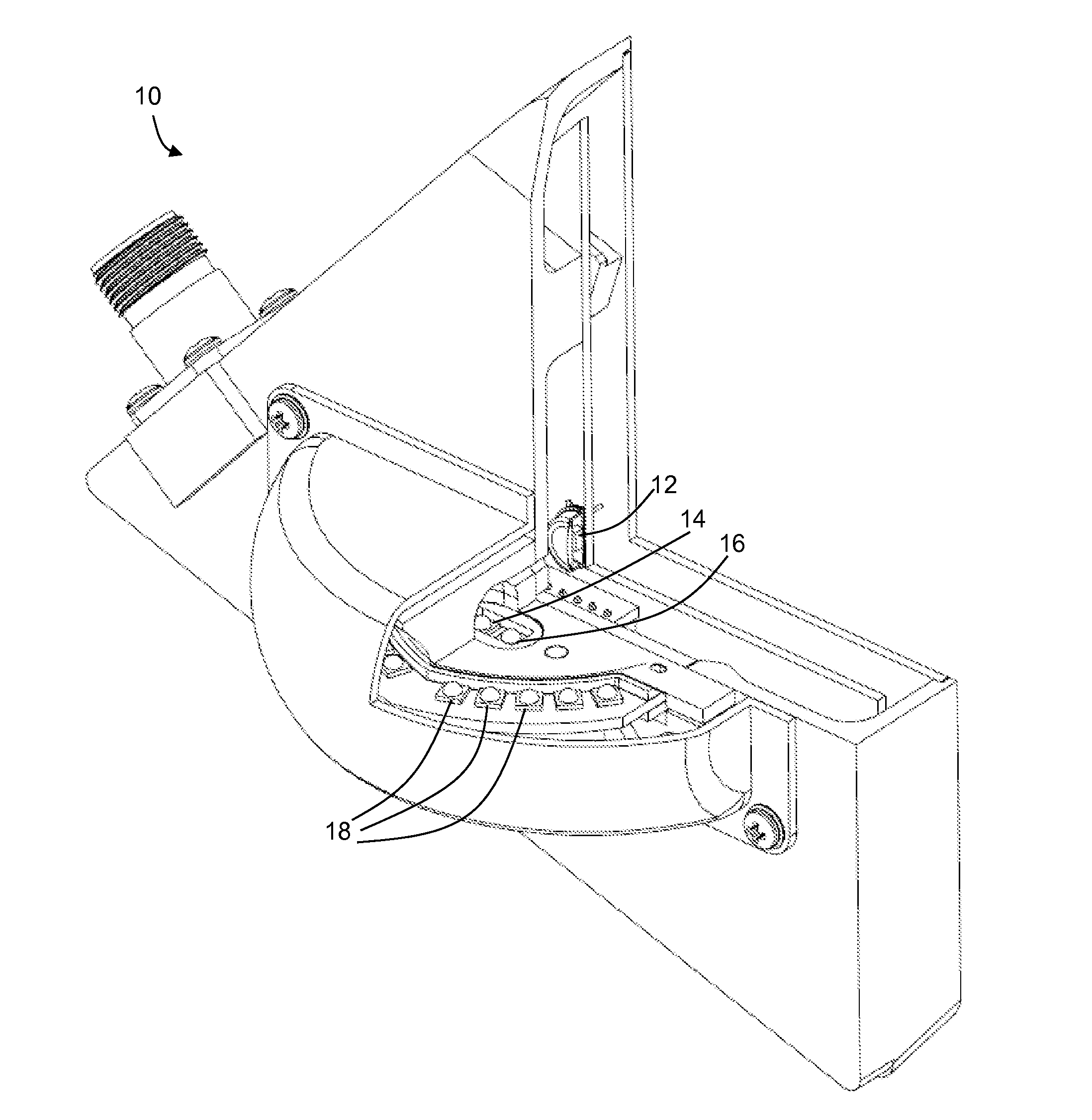
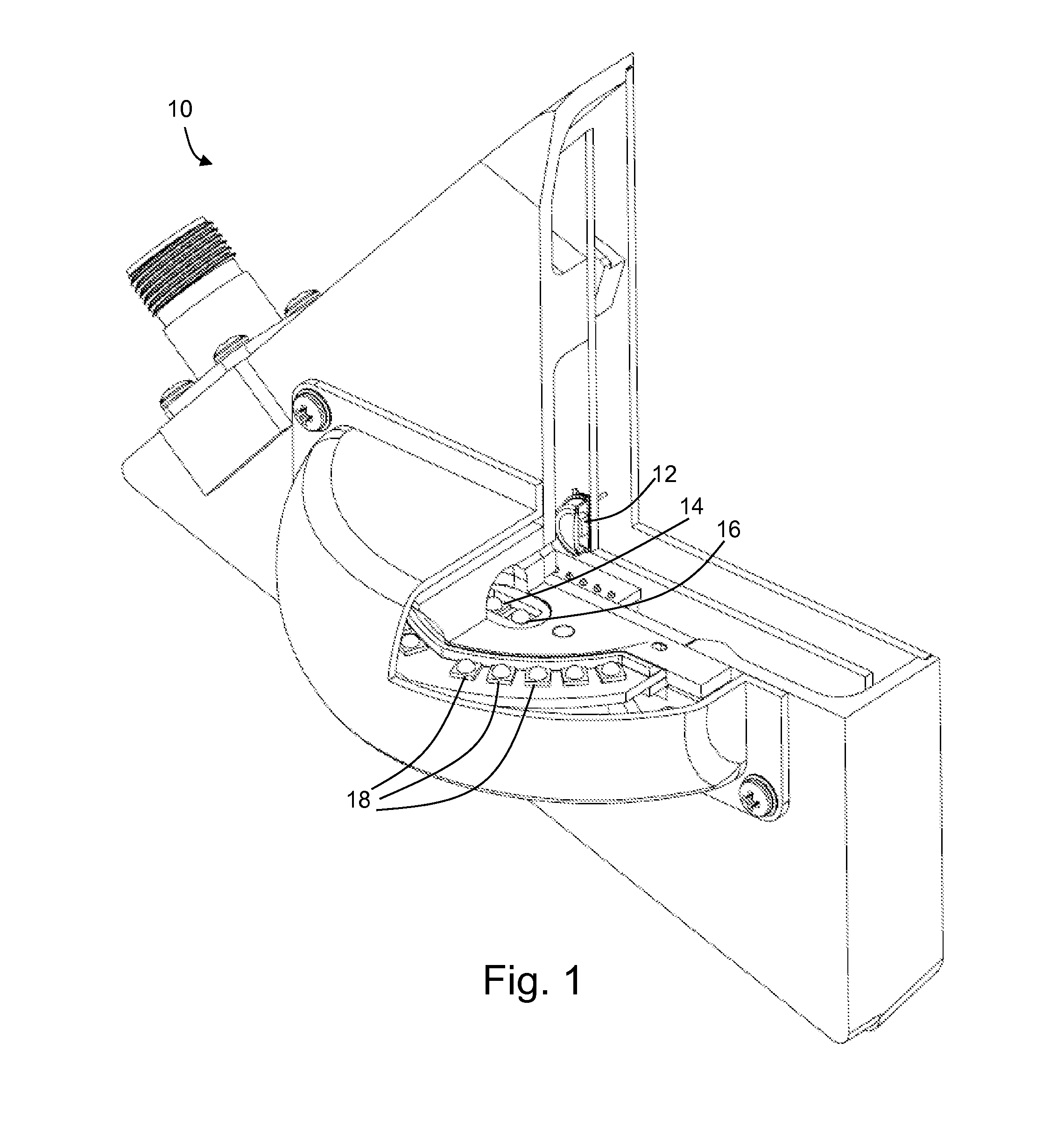
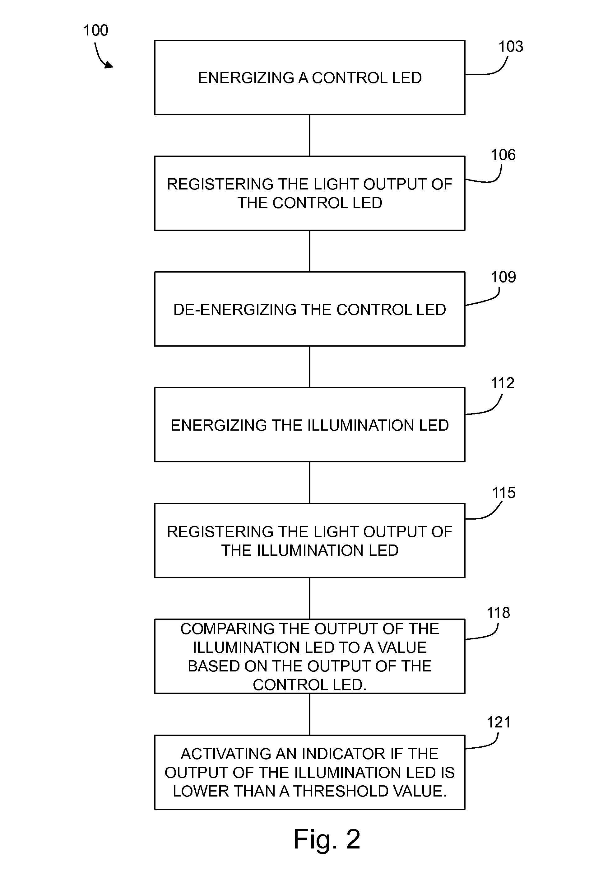
[0017]The present invention may be embodied as a method 100 for determining end of life (“EOL”) of a light fixture, for example, an LED light fixture (the present disclosure may be used with other light technologies, especially those which have output degradation over the lifespan). The method 100 comprises energizing 103 a control LED. The control LED is an LED in the light fixture which is operated for a short period of time relative to the operation of other LEDs in the light fixture. As such, the degradation of the control LED may be assumed to be negligible because it is operated for a relatively small total of number of hours. Once the control LED is energized 103, a sensor is used to register 106 the light output of the control LED. The sensor may be, for example, a photo-diode. The sensor is configured to detect (for example, to measure) the light output of the control LED.

[0018]The light output of an LED may vary upon start-up of the LED, leveling off once the LED has stabi...


PUM


Abstract

The present invention provides methods and devices for determining end of life of a light fixture by comparing the light output of a control LED of the fixture with the light output of an illumination LED of the fixture. The control LED is energized for a short period of time for the purpose of measuring its light output. The illumination LED is energized for the duration of time of the light fixture itself. In this way, the amount of degradation of the illumination LED can be determined by comparison with the control LED. If the light output of the illumination LED falls below a threshold level, actions may be take, such as, for example, sounding an alarm.

Description

CROSS-REFERENCE TO RELATED APPLICATIONS[0001]This application claims priority to U.S. Provisional Application No. 61 / 840,895, filed on Jun. 28, 2013, now pending, the disclosure of which is incorporated herein by reference.FIELD OF THE INVENTION[0002]The disclosure relates to lighting fixtures, and more particularly to methods and systems for determining end of life of a lighting fixture.BACKGROUND OF THE INVENTION[0003]Governmental agencies administer requirements with respect to the lighting requirements of an aircraft. For example, the U.S. Federal Aviation Administration (“FAA”) requires certain minimum lighting requirements including locations of lights, color, and visibility (corresponding to light output).[0004]Light-emitting diodes (“LEDs”) are advantageously used to provide lighting because LEDs are energy efficient relative to previous technologies, and because, as solid-state devices, LEDs have long lifetimes compared with other technologies. LED light fixtures have becom...

Claims


Application Information

Patent Timeline
IPC IPC(8): G01J1/16G01J1/44
CPCG01J1/16G01J2001/4252G01J1/44G01J3/505G01N2201/0623H05B45/58
Inventor LENDARO, JEFFERY BASIL
Owner ASTRONICS
Why Eureka
Eureka Blog
Learn More