Convertible, self adjusting, multimodal strap system for carrying bags and packs
Active Publication Date: 2016-06-30
WHITEHILL ANN
2 Cites 14 Cited by
AI-Extracted Technical Summary
Problems solved by technology
However, it is not always the case that a user will only desire to use packs in a single carrying mode.
Because it is often impractical to continually switch contents between separate bags, such users have sometimes attempted to use strap systems in a mode for which it was not intended, e.g., only using a single strap of a two-arm strap system or manipulating a single arm system so that the pack is positioned on the user's back.
Misusing the strap systems in these fashion is often uncomfortable or unstable.
Most often however, these depend on extra straps and hardware that increase costs, can be unsightly, and ca...
Method used
[0055]The illustrated pack 112 includes at least one internal compartment having an opening 124 at a top end thereof. The opening 124 may be covered by a flap that can be opened to access the compartment. It will be appreciated that the opening 124 may alternatively be closed by a zipper or other mechanism or left open. The pack 112 can be maintained in an upright position in any carrying mode and throughout transitions therebetween. Consequently, there is reduced concern about spilling items from the opening 124 during use even if the opening 124 is not secured. The pack 112 may further include external pockets for easy access.
[0057]The strap system 100 in the illustrated embodiment is formed from two straps 102 and 104 formed as loops of material. Each of the straps 102 and 104 preferably has a total length of between about 30 and 50 inches, for example, between about 38 and 42 inches. This strap dimension has been found to provide comfortable positioning of the pack 112 in each carrying mode as well easy transitions therebetween. The illustrated straps have a width of between 1 to 2 inches, for example, about 1.5 inches.
[0063]A few advantageous features of the invention can be noted in relation to the drawings of FIGS. 3A-3E. First, the transition between carrying configurations can be accomplished without manipulating any snaps, buckles, or other attachment mechanisms. Rather, the user 300 simply manipulates the straps 226 and 228. The straps 226 and 228 are continuously connected to the connection mechanisms 206 and 208 as well the linkage assembly 210 throughout the transitions and the straps 226 and 228 simply slide in relation to the connection mechanisms 206 and 208 and linkage assembly 210. In addition, the pack 200 remains in an upright position in each of the carrying configurations as well as throughout the transition there between. Accordingly, there is reduced concern about movement or spillage of the contents of the pack 200. Moreover, it is not necessar...
Benefits of technology
[0031]3. The simplicity and elegance of the design lend themselves to many high fashion applications where current solutions are deemed too unattractive to be used.
[0032]In accordance with one aspect of the present invention, a convertible strap system is provided. The system includes a strap assembly consisting of one or more straps of material and first and second attachment mechanisms for attaching ...
Abstract
A multi-mode strap system (100) is convertible between a single arm shoulder bag configuration, a two armed backpack configuration, and a single armed cross body configuration. The strap system (100) includes first and second straps (102 and 104), first and second attachment mechanisms (106 and 108) and a linkage assembly (110). The attachment mechanisms (106 and 108) and linkage assembly (110) allow the straps (102 and 104) to move or slide freely during transitions between the three configurations. The transitions can thus be accomplished without manipulating and straps or buckles and without having to remove the pack, and the pack remains upright during transitions.
Application Domain
Travelling sacksPurses +3
Technology Topic
EngineeringSelf adjusting
Image
Examples
- Experimental program(1)
Example
[0046]In the following description, a number of embodiments of the invention are described. These embodiments collectively illustrate various aspects of the invention. It will be understood that many other embodiments and implementations of the invention are possible. Accordingly, the description below should be understood as exemplifying the invention and not by way of limitation. For example, it will be understood that various other shapes, styles, and configurations of the pack are possible and that many other shapes, dimensions, materials, and configurations of the convertible strap system are also possible.
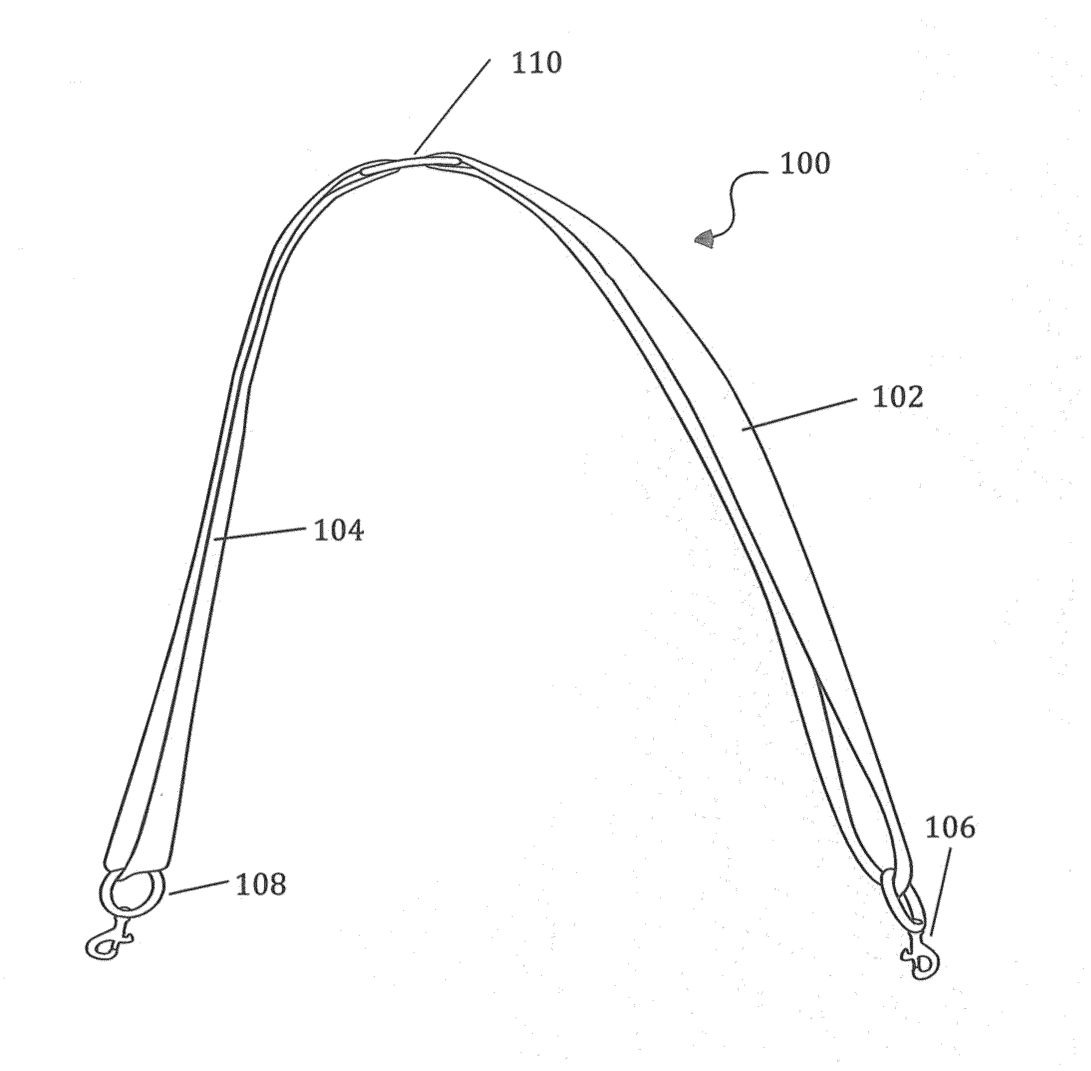
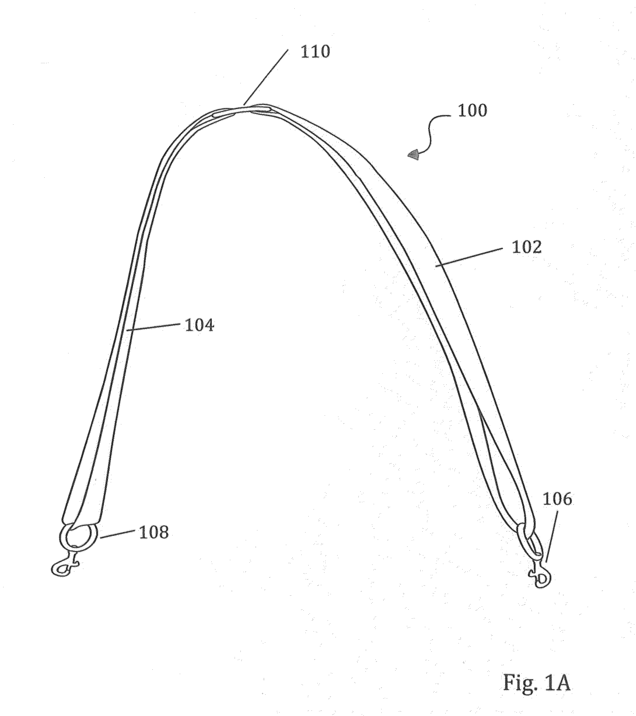
[0047]Referring to FIG. 1A, a perspective view of a strap system 100 in accordance with the present invention is shown. The strap system 100 includes first and second straps 102 and 104. In the illustrated embodiment, each of the straps 102 or 104 is formed as a continuous loop of material such as leather, vinyl, or fabric. For example, each of the straps 102 and 104 may be formed from a strip of leather sewn or otherwise attached together at the ends thereof to form a continuous loop. It is also possible for the strap loops 102 and 104 to be constructed with a strap length adjustment mechanism as will be show in FIG. 1B. The illustrated strap system 100 further includes first and second attachment mechanisms 106 and 108 and a linkage assembly 110. The attachment mechanisms 106 and 108 are used to attach the strap system 100 to a pack or bag as will be described in more detail below. Each of the attachment mechanisms 106 and 108 may be comprised of an almost limitless variety of combinations of snaps, loops, clasps and other pieces, including one or more loops of material. In this example attachment mechanisms 106 and 108 are O-ring swivel snap hooks, but an endless variety of attachments are possible, several of which will be illustrated in later drawings.
[0048]Preferably, each of the attachment mechanisms 106 and 108 allows a corresponding strap 102 or 104 to move or slide freely therethrough during transitions between the three carrying modes—shoulder bag, backpack, and cross body bag, as will be described in more detail below. In this regard, each of the attachment mechanisms 106 and 108 may include a smooth ring of a variety of shapes, D rings, 0-rings, or rectangular rings for example, formed from metal, plastic, or other suitable material. The straps 102 and 104 may be threaded through the ring before the ends of the straps 102 and 104 are connected to form a strap loop, or attachment mechanisms 106 and 108 may be constructed in a manner that allows them to be attached to the strap loops 102 and 104 after they are formed into a loop.
[0049]Where the strap system 100 is provided as an aftermarket product for attachment to a separately purchased pack, the attachment mechanisms 106 and 108 may be adapted for such interconnection. For example, the attachment mechanisms 106 and 108 may include a ring formed from helically wound material, like a key chain, such that the ring can receive attachment structure of a pack. Alternatively, the attachment mechanisms 106 and 108 may include a ring that opens like a jewelry clasp to receive attachment structure of a pack. As a still further alternative, a separate strap of material or ring may be provided as part of the attachment mechanisms 106 and 108 to interconnect a ring of the attachment mechanisms 106 and 108 to attachment structure of a pack. Many other connection options are possible.
[0050]FIG. 1B illustrates the strapping system 100 of FIG. 1A expanded into the two armed backpack carrying mode. Also shown are strap adjustment mechanisms 107 and 109, in this case, slide buckles that may be incorporated into the strap systems 100 and 200 as needed.
[0051]FIG. 2A illustrates the strap system 100 of FIG. 1A attached to a pack 112. The pack 112 may be any type of pack, either provided together with the strap system or separately purchased by the user such as a purse, a messenger bag, a book bag, an item of luggage, a brief case, a computer bag, a tote, or the like. The illustrated pack 112 includes conventional attachment structures 114 and 116. For purposes of illustration the attachment structures 114 and 116 are shown as loops of leather disposed at the upper corners of the pack 112. However, it will be appreciated that the strap system 100 can be attached to a variety of types of attachment structures 114 and 116.
[0052]It will be appreciated that the rings of the attachment mechanisms 106′ and 108′ and of the attachment structures 114 and 116 may be directly interconnected as shown, or they may be connected by a variety of combinations of strap loops and ring or other connecting combinations.
[0053]The attachment mechanisms 106′ and 108′ are preferably disposed on the pack 112 at locations above a horizontal centerline 210 of the pack 112 when the pack is in an upright position as illustrated. In this manner, the center of mass of the pack 112 will generally be below the attachment locations so that the pack hangs stably when the pack 112 is lifted using the strap system 100. In addition, the attachment locations of the attachment structures 114 are preferably disposed on opposite sides of a vertical centerline 122 of the pack 112. It will thus be appreciated that there is significant flexibility in positioning the attachment structures 114 so as to accommodate various aesthetic and structural objectives. It will be appreciated that the strap system 100 may be attached to the pack 112 at other locations (e.g., below horizontal centerline 120) and a separate securing mechanism, such as a loop of material above the horizontal centerline 120, may be used to secure the straps in a secure position. In the illustrated embodiment, the attachment structures 114 are disposed at upper corner portions of the pack 112, e.g., at or adjacent to the corners of the pack 112.
[0054]The size and configuration of the pack 112 may be varied depending on the intended use of the pack and other design considerations. For example, the pack 112 may be a purse, briefcase, computer bag, item of luggage, book bag, or other type of pack. The pack 112 may include a single internal compartment 218 or multiple internal compartments. The compartment(s) may extend substantially across the full width and height of the pack 112 or only a portion thereof. In the illustrated embodiment, the pack 112 is a multi-purpose pack and may include internal compartments for holding a standard laptop computer as well as pockets for holding pens, pencils, business cards, and other items.
[0055]The illustrated pack 112 includes at least one internal compartment having an opening 124 at a top end thereof. The opening 124 may be covered by a flap that can be opened to access the compartment. It will be appreciated that the opening 124 may alternatively be closed by a zipper or other mechanism or left open. The pack 112 can be maintained in an upright position in any carrying mode and throughout transitions therebetween. Consequently, there is reduced concern about spilling items from the opening 124 during use even if the opening 124 is not secured. The pack 112 may further include external pockets for easy access.
[0056]It will be appreciated that the size, shape, configuration, and materials used for constructing the pack 112 may be varied depending on the intended use of the pack 112 and other design considerations. In the illustrated embodiment, the pack 112 and the straps of the strap system 100 are formed primarily from leather. The attachment mechanisms 106′ and 108′ and the linkage assembly 110 are formed from suitably sized metal rings. The pack 112 has a width and height suitable to carry standard laptop computers. In this regard, the width of the pack is preferably at least about 14 inches and more preferably at least about 17 inches. The height of the pack 112 is preferably at least about 10 inches and more preferably at least about 12 inches. The thickness in the illustrated pack 112 is preferably between 1 and 10 inches, for example, between about 2 inches and 5 inches.
[0057]The strap system 100 in the illustrated embodiment is formed from two straps 102 and 104 formed as loops of material. Each of the straps 102 and 104 preferably has a total length of between about 30 and 50 inches, for example, between about 38 and 42 inches. This strap dimension has been found to provide comfortable positioning of the pack 112 in each carrying mode as well easy transitions therebetween. The illustrated straps have a width of between 1 to 2 inches, for example, about 1.5 inches.
[0058]The attachment mechanisms 106′ and 108′ and the linkage assembly 110 are dimensioned and designed to allow the straps 102 and 104 to move freely during transitions as described below. In this regard, the attachment mechanisms 106′ and 108′ and the linkage assembly 110 preferably have a dimension that is at least equal to and, preferably, slightly greater than the width of the straps 102 and 104. For example, each of the attachment mechanisms 106′ and 108′ and the linkage assembly 110 may have an internal opening dimension of about 1¾ inches.
[0059]FIG. 2B illustrates the strap system 100 from FIG. 1B connected to a pack.
[0060]FIG. 2C illustrates the strap system 100 from FIG. 1A connected to a pack 112 worn in the cross body, messenger bag position.
[0061]FIGS. 3A-3E illustrate certain carrying modes of the pack of FIG. 2 as well as a process for transitions therebetween. FIG. 3A shows a user 300 using the pack 200 in a single arm carrying mode. In this mode, the strap system 202 defines a single opening 304, the user inserts one arm through the opening 304 so that the strap system 202 rests on the user's shoulder. In this carrying mode, the pack body 204 rests comfortably against the user's side, for example, against the user's hip depending on the length of the strap system 202.
[0062]To initiate a transition from the single arm carrying mode of FIG. 3A to a two-arm carrying mode, the user can insert an arm through a loop formed by a first strap 226 as shown in FIG. 3B. Next, the user can insert his or her other arm through the loop formed by the other strap 228 as shown in FIG. 3C. The user 300 can then pull each of the straps 226 and 228 over his or her shoulders (see FIG. 3D) until the pack 200 is disposed in the two-arm configuration as shown in FIG. 3E. Ideally, the linkage mechanism 210 is disposed substantially at the center of the user's back in the two-arm carrying configuration and pack body 204 is stably centered on the user's back. This process can simply be reversed to transition from the two-arm carrying configuration of FIG. 3E back to the single arm carrying configuration of FIG. 3A.
[0063]A few advantageous features of the invention can be noted in relation to the drawings of FIGS. 3A-3E. First, the transition between carrying configurations can be accomplished without manipulating any snaps, buckles, or other attachment mechanisms. Rather, the user 300 simply manipulates the straps 226 and 228. The straps 226 and 228 are continuously connected to the connection mechanisms 206 and 208 as well the linkage assembly 210 throughout the transitions and the straps 226 and 228 simply slide in relation to the connection mechanisms 206 and 208 and linkage assembly 210. In addition, the pack 200 remains in an upright position in each of the carrying configurations as well as throughout the transition there between. Accordingly, there is reduced concern about movement or spillage of the contents of the pack 200. Moreover, it is not necessary for the user 300 to set the pack 200 down in order to accomplish a transition between the carrying modes. Rather, the pack 200 can remain supported by at least one shoulder of the user 300 throughout the process. Accordingly, transitioning between carrying modes is simple, convenient, and can be accomplished without concern that the pack will get dirty, wet, or otherwise damaged due to having to set the pack down.
[0064]FIGS. 4A-4B show an alternative embodiment of a pack 400 in accordance with the present invention in the single arm carrying configuration and the two-arm carrying configuration, respectively. The illustrated pack 400 includes a pack body 404, attachment structures 414 and 416 attachment mechanisms 406 and 408, (with alternate mechanisms 406′ and 408′ shown in FIG. 4B) and straps 426 and 428 which can all be constructed generally as described above in connection with FIG. 2 (though the length of the straps 426 and 428 may be varied in relation to the embodiment of FIG. 2).
[0065]However, the illustrated pack 400 includes a different linkage assembly 430 for connecting the straps 426 and 428. In particular, the illustrated linkage assembly 430 includes first and second rings 432 and 434 and a linkage strap 436. Such a linkage assembly 430 may be desired for aesthetic and/or structural reasons. For example, the illustrated linkage assembly 430 can be used to accommodate different positioning of the pack body 404 on the user in one or both of the carrying modes in relation to the design of FIG. 2. For example, by appropriate selection of the lengths of the straps 426, 428, and 436, the pack body 404 can ride higher or lower on the user's back or side in the one arm and/or two-arm carrying modes. As shown in FIG. 4B, in the two-arm carrying configuration, the vertical position of the pack body 404 on the user's back is determined by the length of the straps 426 and 428 (which are preferably of equal length), whereas the position of the pack body 404 in the single arm carrying configuration depends not only on the lengths of the straps 426 and 428, but also depends on the length of the strap 436. In this regard, if the strap 436 is sufficiently long so that it is not in significant tension in the two-arm carrying mode, the strap 436 can be easily moved up or down, as shown by arrow 437, as may be desired for aesthetics or to get the strap 436 out of the way. Moreover, the design of FIGS. 4A-4B can assist in spreading the weight of the pack 400 on the user's back or provide a more comfortable handle for carrying the pack 400 by hand.
[0066]The illustrated rings 432 and 434 may be circular or other shaped rings and may have an internal opening dimension of about 1¾ inches. The strap 436 may be formed from leather having a width of about 1½ inches. The total length of the strap 436 may be between about 6 inches and 18 inches, for example, between about 8 inches and 12 inches. The straps 426 and 428 may be shortened in relation to the straps of FIGS. 2A-2B. For example, the straps 426 and 428 may be shortened such that the overall length of the strap system 404 of FIG. 4 is similar to the overall length of the strap system 202 of FIGS. 2A-2B.
[0067]The foregoing description of the present invention has been presented for purposes of illustration and description. Furthermore, the description is not intended to limit the invention to the form disclosed herein. Consequently, variations and modifications commensurate with the above teachings, and skill and knowledge of the relevant art, are within the scope of the present invention. The embodiments described hereinabove are further intended to explain best modes known of practicing the invention and to enable others skilled in the art to utilize the invention in such, or other embodiments and with various modifications required by the particular application(s) or use(s) of the present invention. It is intended that the appended claims be construed to include alternative embodiments to the extent permitted by the prior art.
PUM


Description & Claims & Application Information
We can also present the details of the Description, Claims and Application information to help users get a comprehensive understanding of the technical details of the patent, such as background art, summary of invention, brief description of drawings, description of embodiments, and other original content. On the other hand, users can also determine the specific scope of protection of the technology through the list of claims; as well as understand the changes in the life cycle of the technology with the presentation of the patent timeline. Login to view more.