Clip and rail attachment system

Inactive Publication Date: 2016-06-30
FITNEFF
View PDF4 Cites 46 Cited by
  • Summary
  • Abstract
  • Description
  • Claims
  • Application Information

AI Technical Summary

Problems solved by technology

If insufficient torque is applied, then there is a risk of the clip or clamping member disengaging from the rail or sliding to an undesirable position therealong.
If too much torque is applied, there is a risk of stripp...

Method used


Image

  • Clip and rail attachment system
  • Clip and rail attachment system
  • Clip and rail attachment system

Examples


Embodiment Construction

[0022]The following description is of preferred embodiments by way of example only and without limitation to the combination of features necessary for carrying the invention into effect. Reference is to be had to the Figures in which identical reference numbers identify similar components. The drawing figures are not necessarily to scale and certain features are shown in schematic or diagrammatic form in the interest of clarity and conciseness.

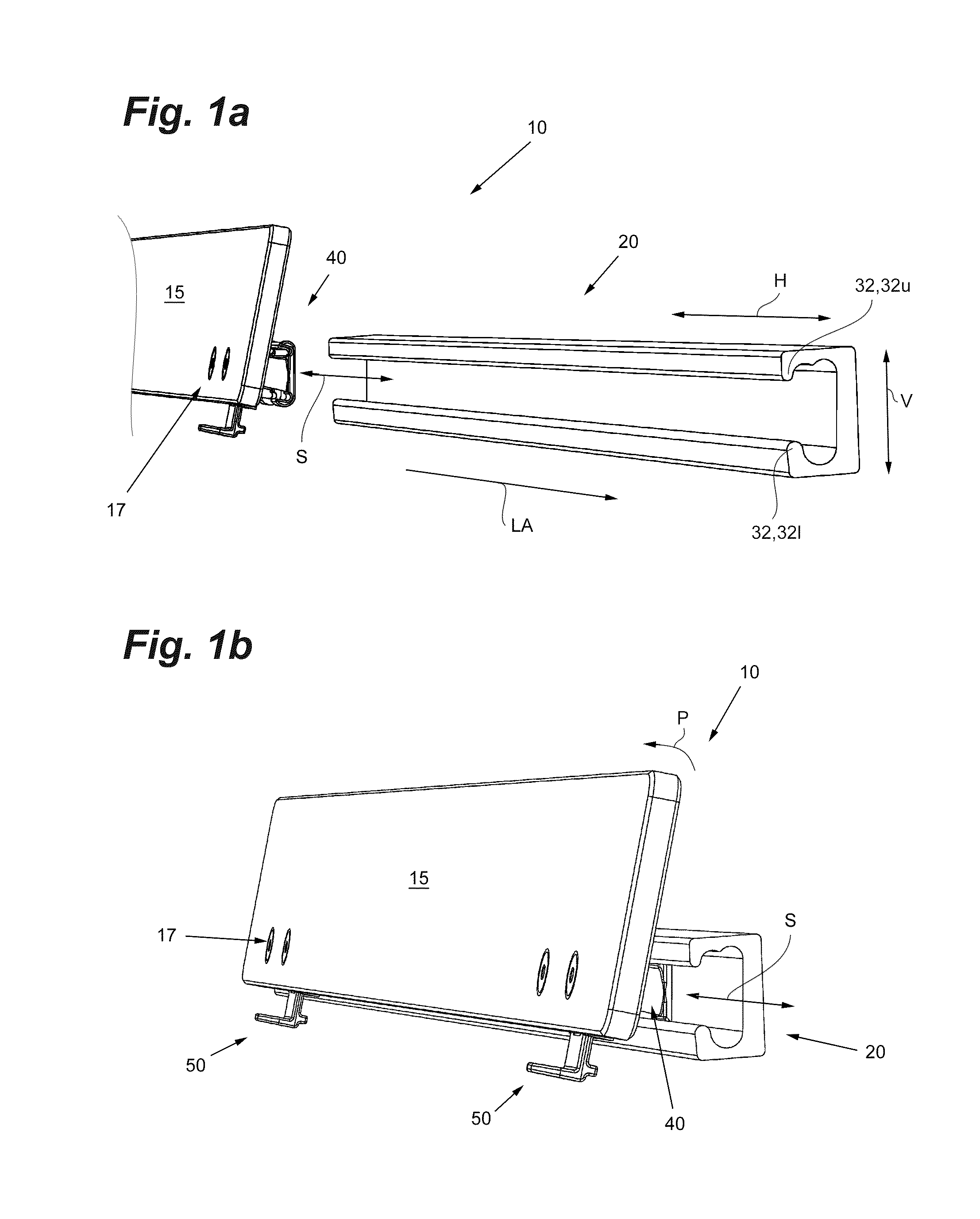
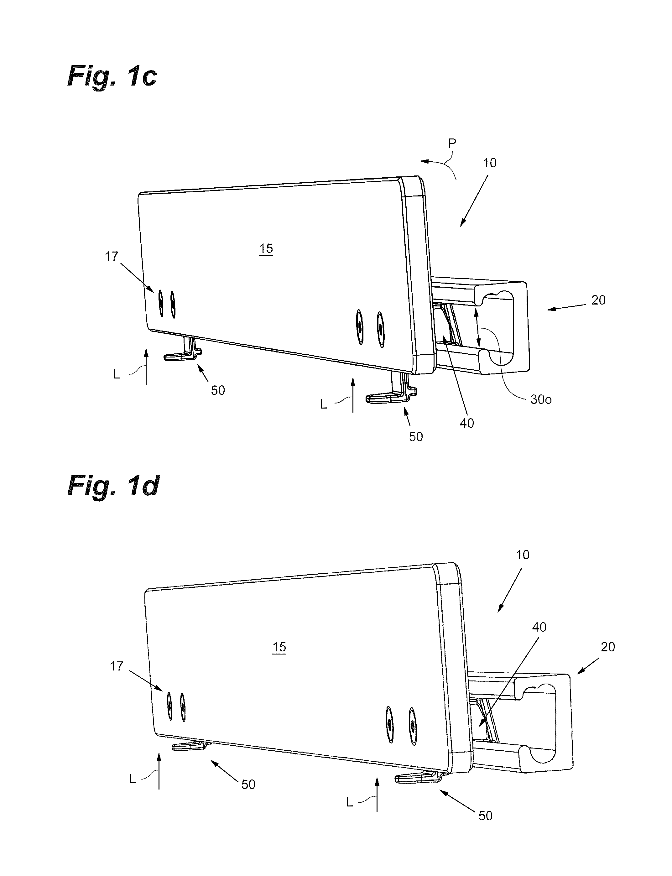
[0023]A first preferred embodiment of the clip and rail attachment system 10 of the present invention is shown in FIGS. 1a-3d and 5a-10b and is designed to be attached in a conventional manner to a piece of equipment or to a surface such as a wall or panel (not shown). The system comprises at least one rail member 20 and at least one rail clip 40 suitable for slidable movement S along the rail member 20 and suitable for supporting and mounting an accessory 15 and supporting same from the rail 20.

[0024]Rail member 20 is preferably an elongate m...


PUM


Abstract

A clip and rail attachment system, for mounting an accessory. comprises at least one rail member having a longitudinal axis, a first end, a second end, a channel that extends substantially along the longitudinal axis, at least one end opening, and a longitudinal opening. The system also comprises at least one rail clip, having a channel engagement member and a mounting member. The rail clip is suitable for slidable movement along the rail member and for supporting the accessory on the mounting member. The channel communicates with the at least one opening and the longitudinal opening allows for the mounting member to extend out from the channel while clip is supported by the rail. The channel and the at least one opening are each of suitable size and dimension to receive the channel engagement member, so as to allow rail clip to be captured by the rail member and to slide therealong in a direction that is substantially parallel to the longitudinal axis.

Description

FIELD OF THE INVENTION[0001]This invention relates generally to attachment devices used to secure accessories onto a piece of equipment or other member. More particularly, the invention relates to slidably adjusting and securing accessories onto an elongate rail or groove in a piece of fitness, office or other equipment.BACKGROUND OF THE INVENTION[0002]The background information discussed below is presented to better illustrate the novelty and usefulness of the present invention. This background information is not admitted prior art.[0003]Existing clip and rail attachment systems typically feature an elongate rail member attached to, or embedded within, a piece of equipment or surface and a plurality of sliding clip or clamping members that are slidably adjustable along, and securable to, the rail member. Usually, such attachment systems feature one or more grooves, slots or channels within the rail to accept a portion of the clip or clamping member and a thumbscrew, knob or bolt on...

Claims


Application Information

Patent Timeline
IPC IPC(8): F16M13/02
CPCF16M2200/025F16M13/022A47F5/0853A47B96/1441F16M11/045A63B1/00
Inventor BETTIN, RON
Owner FITNEFF
Why Eureka
Try Eureka