Flexible conduit connector
- Summary
- Abstract
- Description
- Claims
- Application Information
AI Technical Summary
Benefits of technology
Problems solved by technology
Method used
Image

Examples
Embodiment Construction
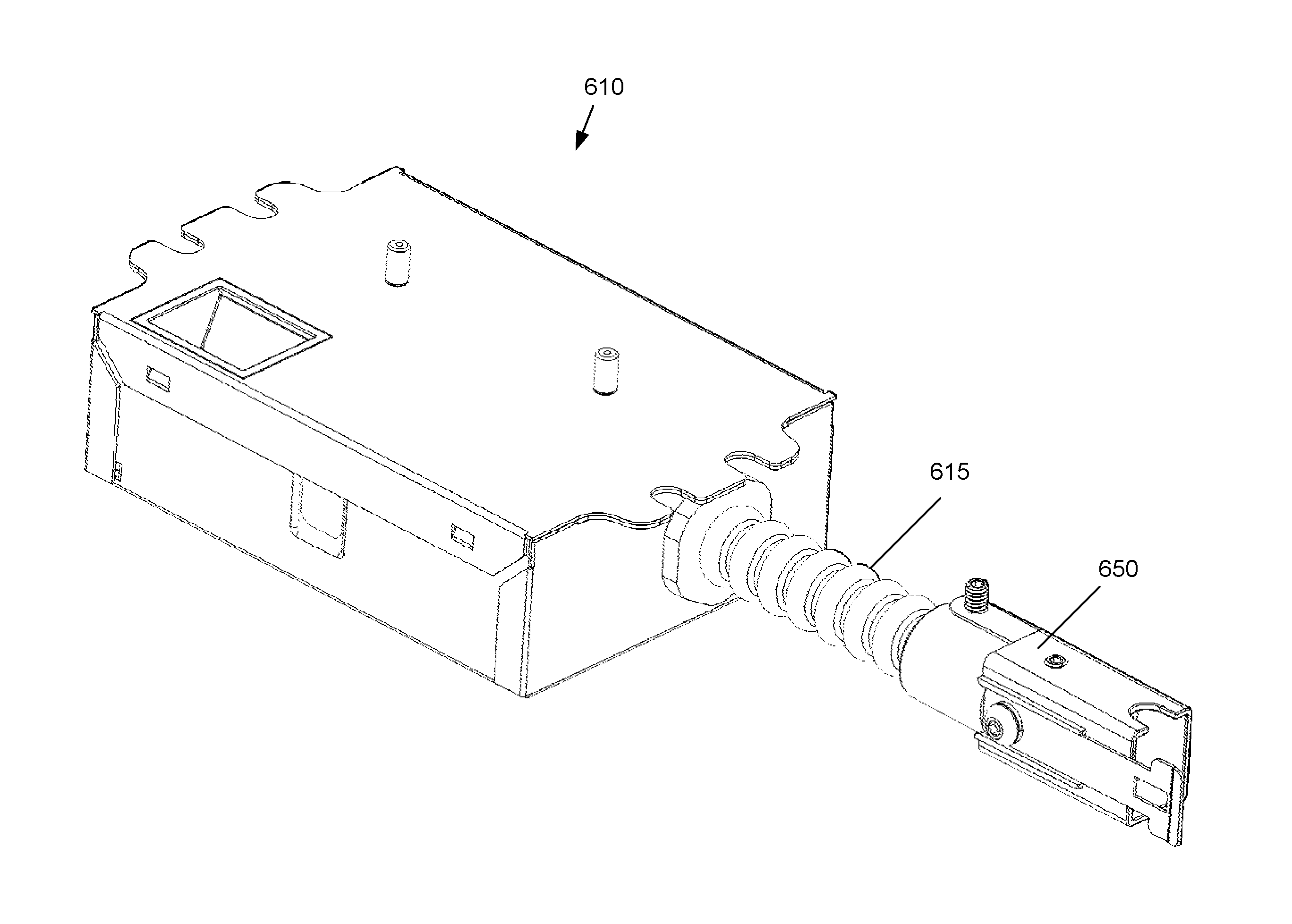
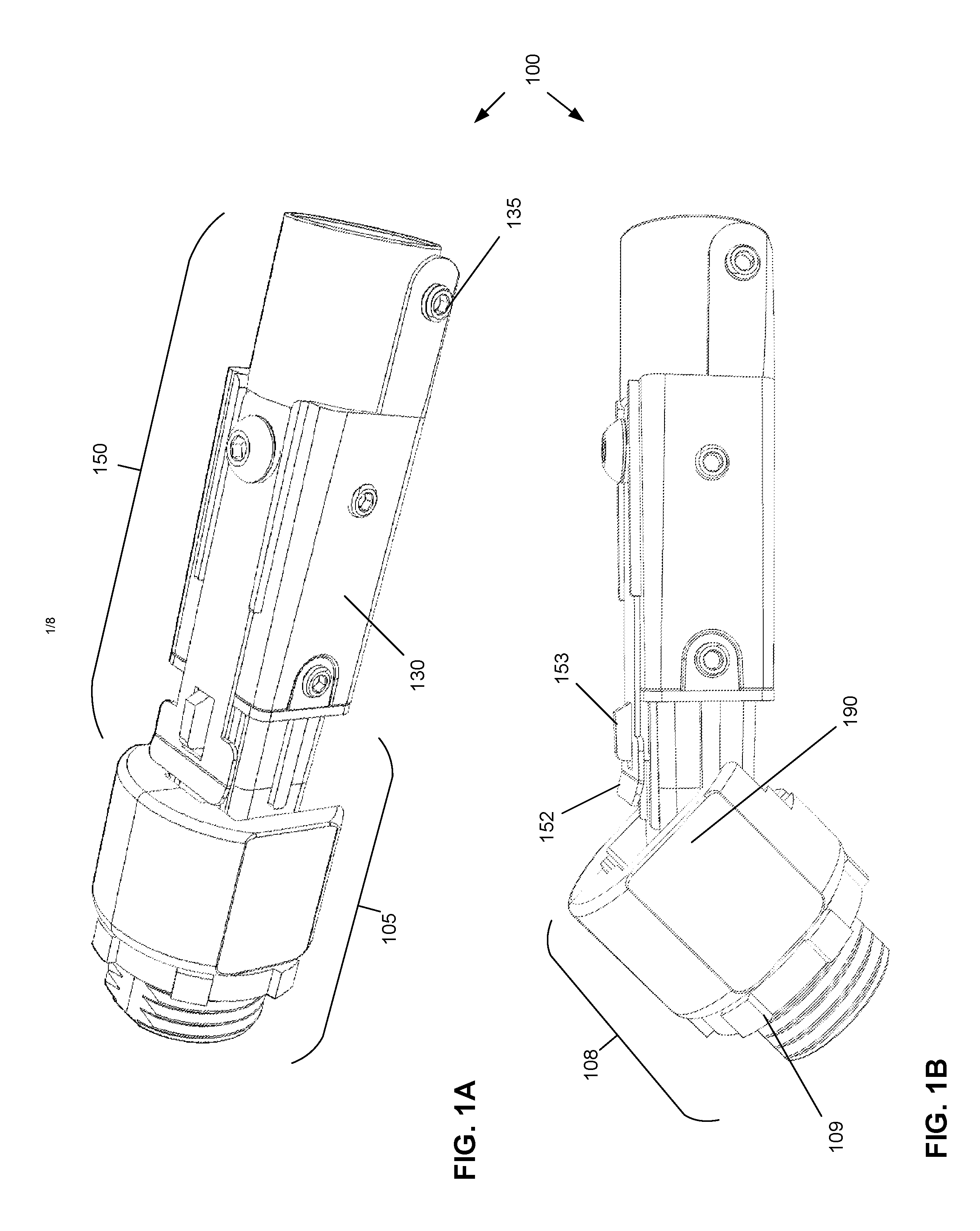
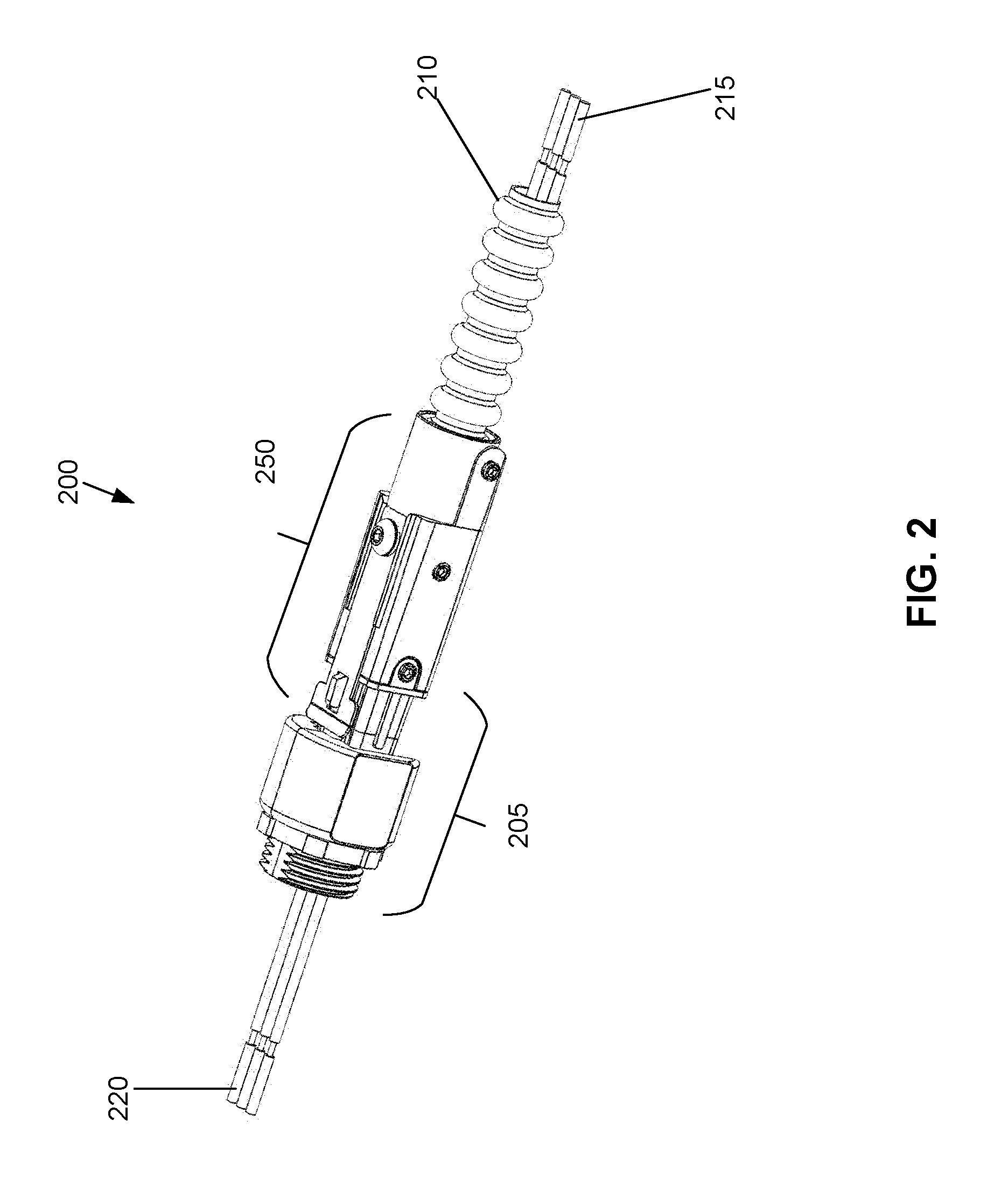
[0021]FIGS. 1A and 1B illustrate an assembled and connected connector system 100 in accordance with various embodiments of the present disclosure. FIG. 1A shows the connector system 100 in a linear configuration, in which two portions of the connection system are extended in a straight line. FIG. 1B shows the same connector system 100 of FIG. 1A, but in a “bent” or “hinged” configuration, wherein two portions are oriented at an angle from one another. Reference numerals used to describe portions of either FIG. 1A or 1B refer to corresponding portions in the other figure. As shown, the first portion 150 of the connector system (or the “conduit end” or “conduit-receiving portion,” or “conduit portion”) connects to (referring briefly to FIG. 2) a flexible conduit 210, securing the end of the flexible conduit 210 within a metal housing 130 via a set screw 135 that engages the corrugated surface of the flexible conduit 210 and locks the conduit 210 in place. The first portion 150 of the ...
PUM
 Abstract
Description
Claims
Application Information
 - R&D Engineer
- R&D Manager
- IP Professional
- Industry Leading Data Capabilities
- Powerful AI technology
- Patent DNA Extraction
Browse by: Latest US Patents, China's latest patents, Technical Efficacy Thesaurus, Application Domain, Technology Topic.
© 2024 PatSnap. All rights reserved.Legal|Privacy policy|Modern Slavery Act Transparency Statement|Sitemap