
Clutter suppression in ultrasonic imaging systems

a technology of ultrasonic imaging and clutter suppression, applied in the field can solve the problems of obstructing data of interest, ultrasonic imaging systems typically produce relatively noisy images, etc., and achieve the effect of reducing the clutter effect of ultrasonic imaging systems

Inactive Publication Date: 2016-07-07
CRYSTALVIEW MEDICAL IMAGING
View PDF0 Cites 3 Cited by
  • Summary
  • Abstract
  • Description
  • Claims
  • Application Information

AI Technical Summary

Benefits of technology

[0014]Embodiments of the present invention provide methods and devices for reducing clutter effects in ultrasonic imaging systems.

Problems solved by technology

Ultrasonic imaging systems typically produce relatively noisy images, making the analysis and / or diagnosis of these images a task for highly trained experts.
One of the most problematic imaging artifacts is clutter, i.e., undesired information that appears in the imaging plane, obstructing data of interest.

Method used


Image

  • Clutter suppression in ultrasonic imaging systems
  • Clutter suppression in ultrasonic imaging systems
  • Clutter suppression in ultrasonic imaging systems

Examples


Embodiment Construction

System Description

[0023]In broad terms, the present invention relates to methods and systems for suppressing clutter effects in ultrasonic imaging systems. In some embodiments, these methods and systems also result in enhancement of the ultrasound images' lateral resolution, i.e., the resolution along directions perpendicular to the centerline of an ultrasound beam.

[0024]Before explaining at least one embodiment of the invention in detail, it is to be understood that the invention is not limited in its application to the details of construction and the arrangement of the components set forth in the following description or illustrated in the drawings. The invention is capable of other embodiments or of being practiced or carried out in various ways. Also, it is to be understood that the phraseology and terminology employed herein is for the purpose of description and should not be regarded as limiting.

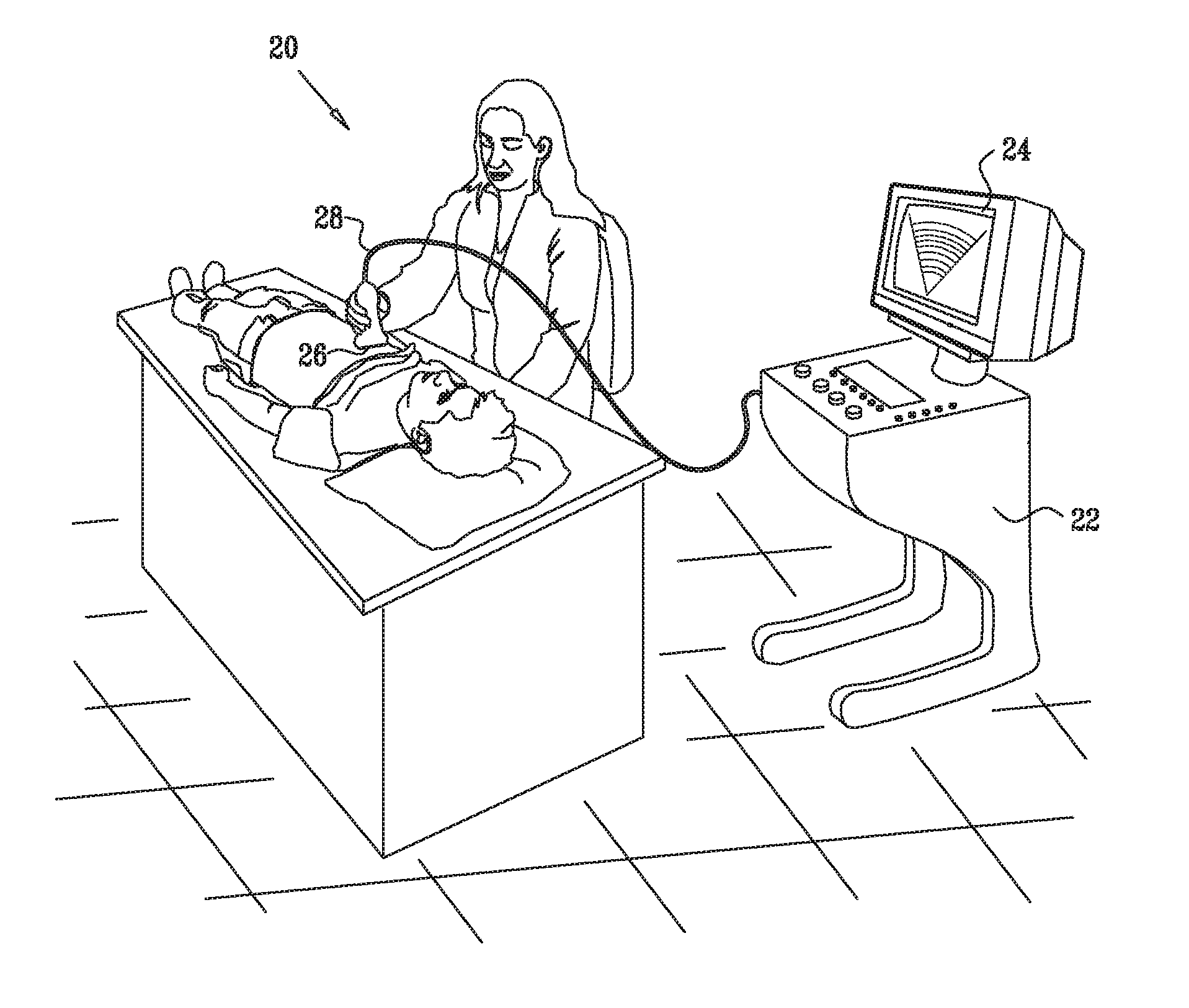
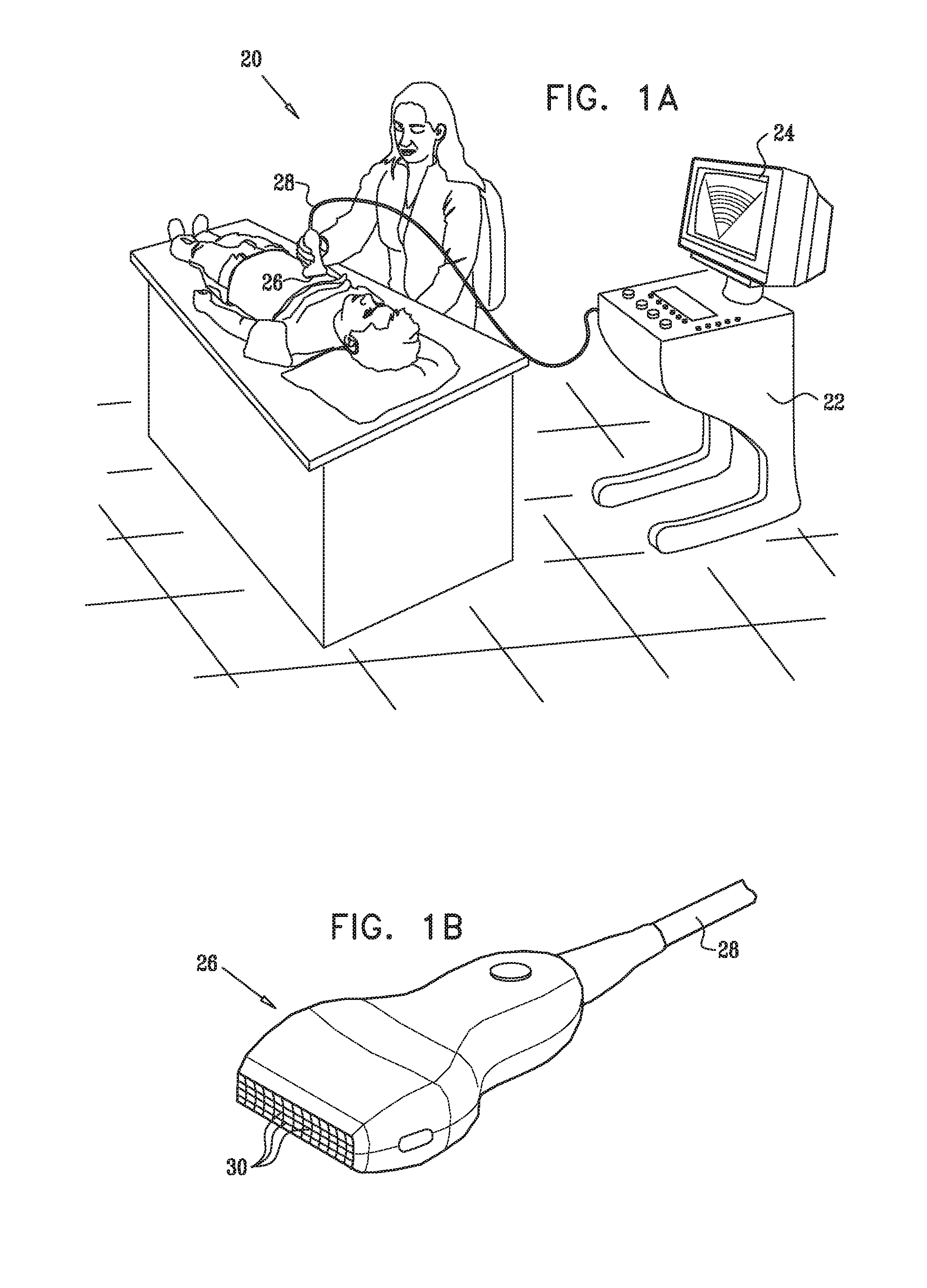
[0025]FIG. 1A is a schematic, pictorial illustration of an ultrasonic imaging syst...


PUM


Abstract

A method of ultrasound imaging is provided herein. The method includes the following stages: transmitting ultrasound radiation towards a target and receiving reflections of the ultrasound radiation from a region of the target in a main reflected signal and one or more auxiliary reflected signals, wherein each one of the reflected signals comprises an input dataset and is associated with a beam with a different and distinct beam pattern; compounding the input datasets from the main reflected signal and one or more auxiliary reflected signals, by the use of a compounding function, said compounding function using parameters derived from spatial analysis of the input datasets.

Description

[0001]This application is a continuation of Ser. No. 13 / 408,136 filed Feb. 29, 2012, which is a continuation-in-part of U.S. patent application Ser. No. 13 / 234,927 filed Sep. 16, 2011, which is a continuation-in-part of U.S. patent application Ser. No. 11 / 722,246 filed on Jun. 20, 2007, now U.S. Pat. No. 8,045,777, issued Oct. 25, 2011, which is a national stage entry of PCT / IL2005 / 001383 filed on Dec. 27, 2005 which claims priority to U.S. Provisional Application Ser. No. 60 / 640,368 filed Dec. 30, 2004, all of which are incorporated herein by reference in their entirety.FIELD OF THE INVENTION[0002]The present invention relates generally to ultrasonic imaging systems, e.g., for medical imaging, and particularly to methods and systems for suppressing clutter effects in ultrasonic imaging systems.BACKGROUND OF THE INVENTION[0003]Ultrasonic medical imaging plays a crucial role in modern medicine, gradually becoming more and more important as new developments enter the market. One of th...

Claims


Application Information

Patent Timeline
Patent Type & Authority Applications(United States)
IPC IPC(8): A61B8/08G01S15/89G01S7/52
CPCA61B8/5207A61B8/488G01S15/8993G01S7/52026G01S7/52047A61B8/483A61B8/4488A61B8/0883G01S7/52077
Inventor ZWIRN, GIL
Owner CRYSTALVIEW MEDICAL IMAGING
Learn More