Clutter suppression in ultrasonic imaging systems

a technology of ultrasonic imaging and suppression, applied in the field can solve the problems of significant signal distortion and obstructing data of interest, and achieve the effect of reducing the clutter effect of ultrasonic imaging systems

Active Publication Date: 2021-02-02
CRYSTALVIEW MEDICAL IMAGING
View PDF16 Cites 0 Cited by
  • Summary
  • Abstract
  • Description
  • Claims
  • Application Information

AI Technical Summary

Benefits of technology

[0017]Embodiments of the present invention provide methods and devices for reducing clutter effects in ultrasonic imaging systems.
[0081]The adjusting the beamforming sample alignment may effectively rotate slanted blobs so as to reduce the absolute value of their blob slope and enhance range resolution.
[0098]The adjusting the beamforming sample alignment may effectively rotate slanted blobs so as to reduce the absolute value of their blob slope and enhance range resolution.

Problems solved by technology

One of the most problematic imaging artifacts is clutter, i.e., undesired information that appears in the imaging plane or volume, obstructing data of interest.
In most cases, objects in the probe's sidelobes cause significant signal distortion if they are highly reflective to ultrasound waves and / or are located in spatial angles for which the probe's sidelobe level is relatively high.

Method used


Image

  • Clutter suppression in ultrasonic imaging systems
  • Clutter suppression in ultrasonic imaging systems
  • Clutter suppression in ultrasonic imaging systems

Examples


example

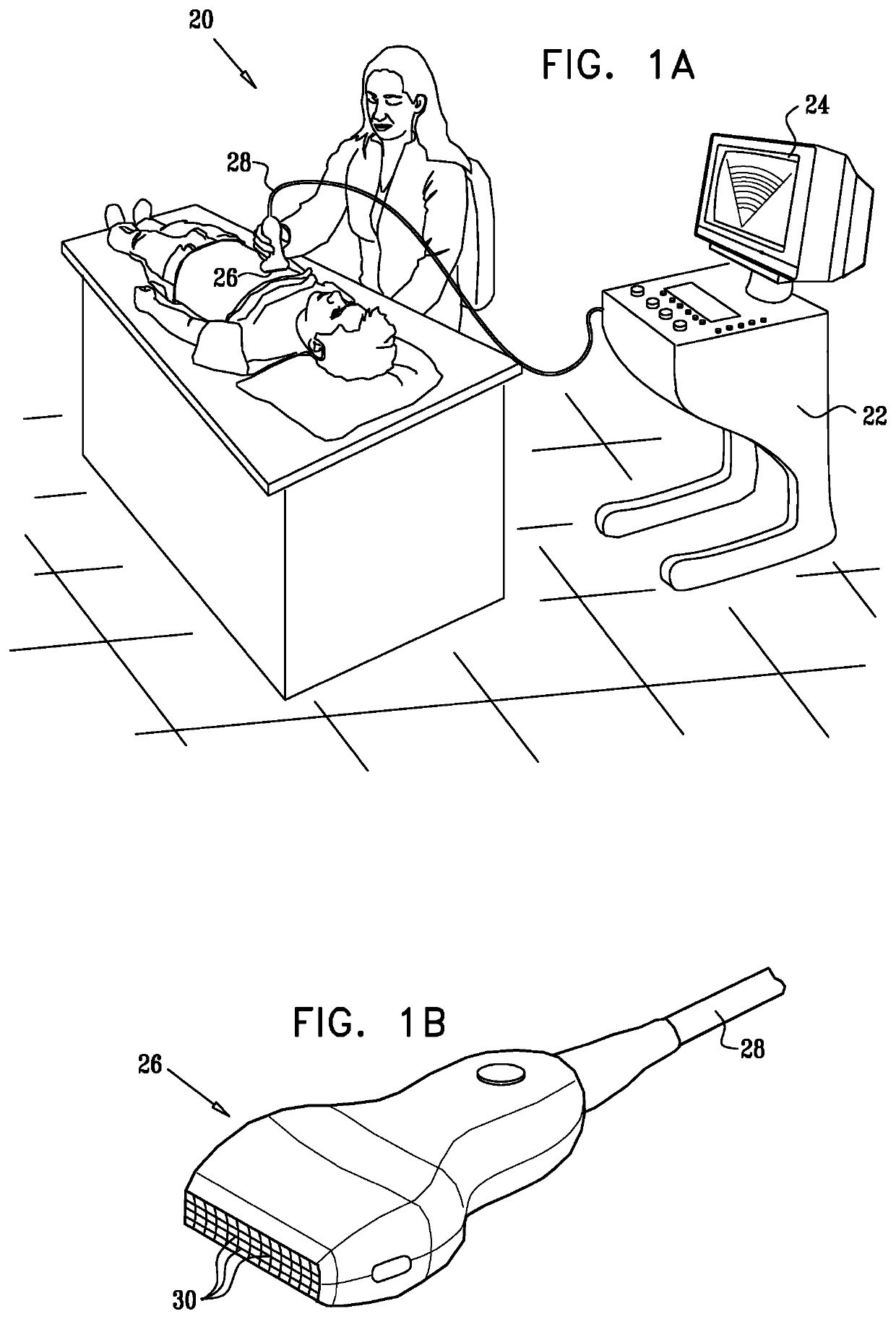
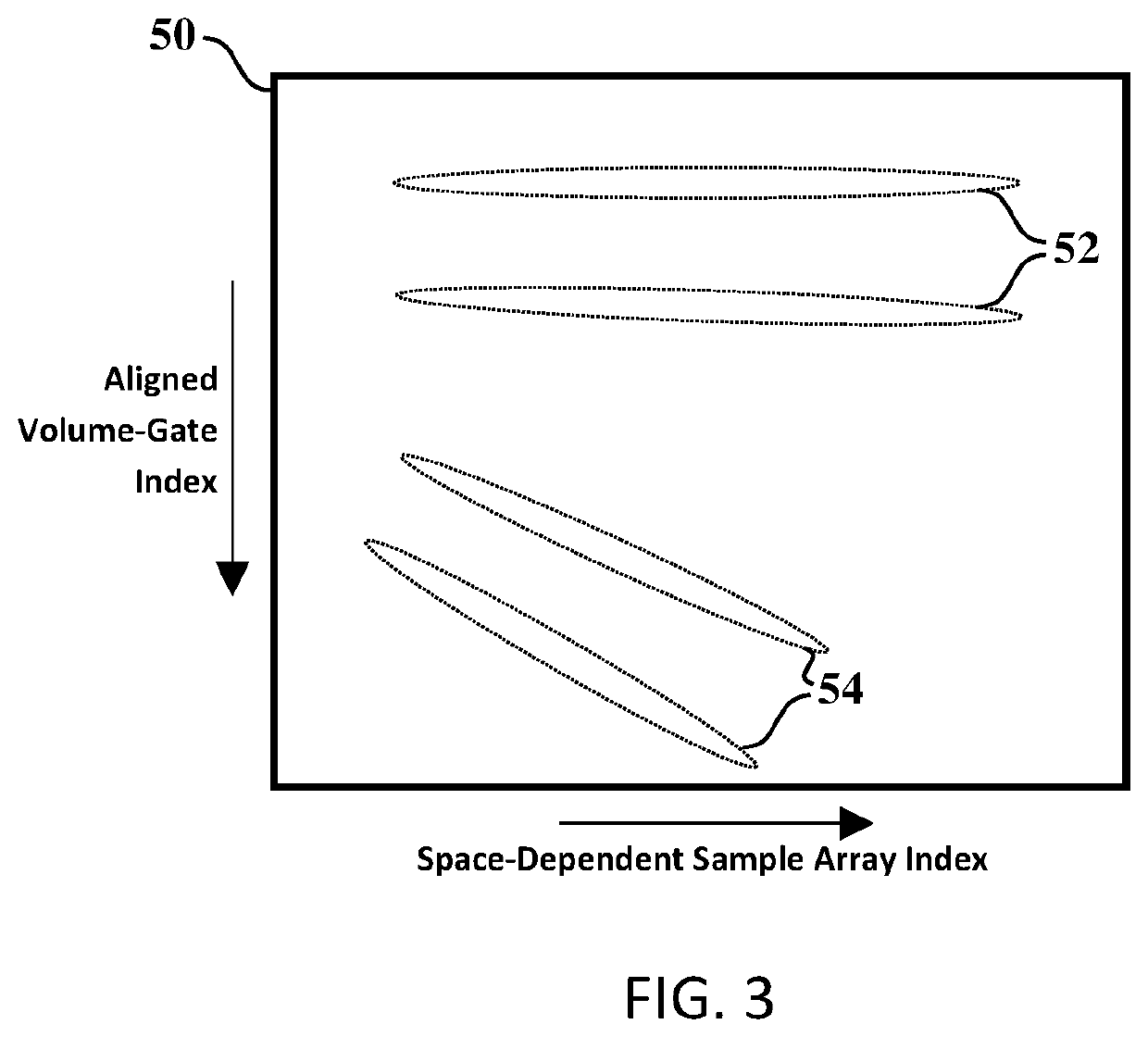
[0411]As an example of an ultrasound apparatus to perform the method, the probe has a one-dimensional transducer array, and per-channel sampling is employed. In the example method, for each receive beam or group or receive beams, for each volume-gate, beamforming sample alignment is applied. Then for each aligned volume-gate, a single clutter suppression feature is computed, in this example the ratio between the number of zero-crossings within the space-dependent sample array and the number of elements turned-on within the space-dependent sample array. That the ratio between the number of zero-crossings and the number of elements turned-on is indicative of the local clutter level can be seen, for example, with reference to FIG. 3. The vertical axis corresponds to the aligned volume-gate index, so each aligned volume-gate corresponds to a row in the figure. A perfectly focused reflector at the center of the beam is expected to produce a horizontal blob (as in 52). In such cases, a si...


PUM


Abstract

Methods of ultrasound imaging, some of which comprise: generating one or more transmit beams, wherein the boresight of each of the transmit beams points to a direction associated with a target region generating one or more receive beams using a probe (26) comprising a transducer array (30); for each receive beam or group of receive beams, sampling the received signal one or more times, wherein each sample is associated with a certain volume within the target region (“volume-gate”), and wherein multiple space-dependent samples are taken over the probe for each volume-gate; and processing the space-dependent samples, said processing comprising: applying beamforming sample alignment such that each space-dependent sample associated with a volume-gate is aligned; for each aligned volume-gate, computing one or more clutter suppression features, wherein a clutter suppression feature is dependent on the signal variability of the space-dependent samples; for each aligned volume-gate, computing a metric value wherein the metric value depends on values of one or more of the one or more clutter suppression features for the aligned volume-gate, and performing a beamforming summation step in accordance with the metric value.

Description

RELATED APPLICATION[0001]This application claims priority from U.S. Provisional Patent Application 62 / 128,525 filed Mar. 5, 2015, the content of which is hereby incorporated by reference.FIELD OF THE INVENTION[0002]The present invention relates generally to ultrasonic imaging systems, e.g., for medical imaging, and particularly to methods and systems for suppressing clutter effects in ultrasonic imaging systems.BACKGROUND OF THE INVENTION[0003]Ultrasonic medical imaging plays a crucial role in modern medicine, gradually becoming more and more important as new developments enter the market. Some of the most common ultrasound imaging applications are cardiac imaging (also referred to as echocardiography), abdominal imaging, and obstetrics and gynecology. Ultrasonic imaging is also used in various other industries, e.g., for flaw detection during hardware manufacturing.[0004]Ultrasound images often include artifacts, making the analysis and / or diagnosis of these images a task for highl...

Claims


Application Information

Patent Timeline
Patent Type & Authority Patents(United States)
IPC IPC(8): G03B42/06G01S7/52G01S15/89A61B8/00
CPCG01S7/52077A61B8/4494G01S7/52047G01S7/52085G01S15/8918G01S15/8997G01S15/8915G01S15/8927A61B8/14G01S7/52026
Inventor ZWIRN, GIL
Owner CRYSTALVIEW MEDICAL IMAGING
Why Eureka
Try Eureka