Clutter suppression in ultrasonic imaging systems

a technology of ultrasonic imaging and suppression of clutter, applied in the field of medical imaging systems, can solve the problems of obstructing the data of interest, ultrasonic imaging systems typically produce noisy images, etc., and achieve the effect of reducing the clutter effect of ultrasonic imaging systems, robust differentiation of clutter, and suppressing clutter

Inactive Publication Date: 2011-10-25
CRYSTALVIEW MEDICAL IMAGING
View PDF8 Cites 14 Cited by
  • Summary
  • Abstract
  • Description
  • Claims
  • Application Information

AI Technical Summary

Benefits of technology

[0010]Embodiments of the present invention provide methods and devices for reducing clutter effects in ultrasonic imaging systems. The disclosed methods are particularly robust in differentiating the clutter from the desired signals, as the methods use signal processing during acquisition of the ultrasound image, as opposed to post-acquisition image-processing methods. In other words, the clutter is suppressed out by processing the received signal samples directly during data acquisition, rather than performing post-processing of the image pixels.

Problems solved by technology

Ultrasonic imaging systems typically produce noisy images, making the diagnosis of these images a task for highly trained expert physicians.
One of the most problematic imaging artifacts is clutter, i.e., undesired information that appears in the imaging plane, obstructing the data of interest.

Method used


Image

  • Clutter suppression in ultrasonic imaging systems
  • Clutter suppression in ultrasonic imaging systems
  • Clutter suppression in ultrasonic imaging systems

Examples


Embodiment Construction

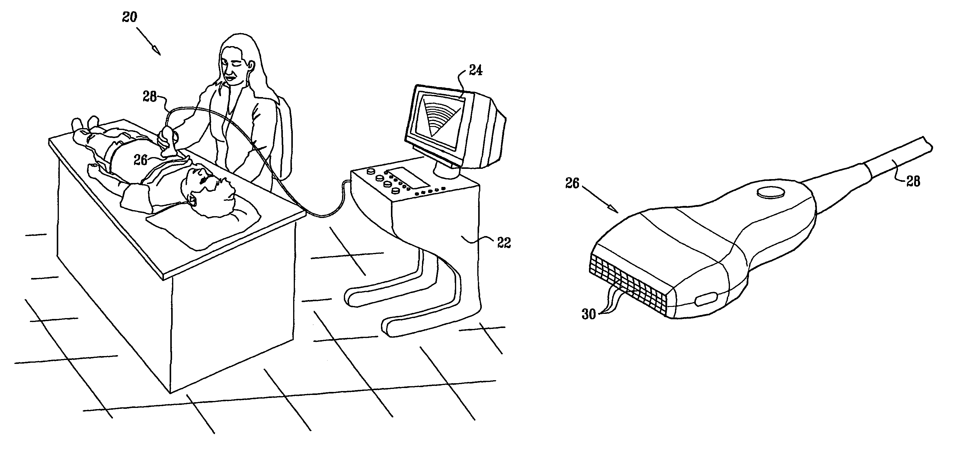
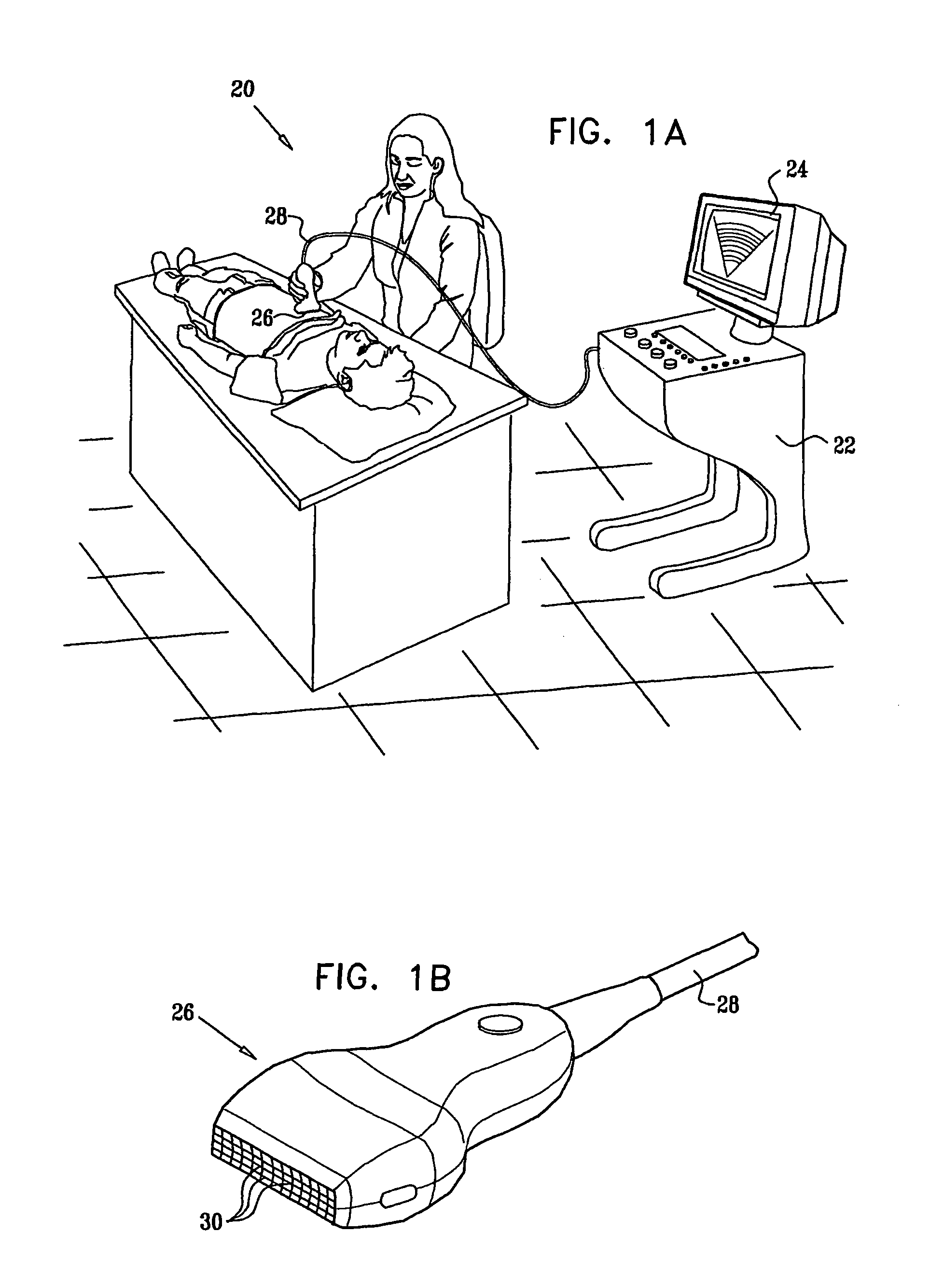
on of an ultrasonic imaging system, in accordance with an embodiment of the present invention;

[0056]FIG. 1B is a schematic, pictorial illustration of a probe used in an ultrasonic imaging system, in accordance with an embodiment of the present invention;

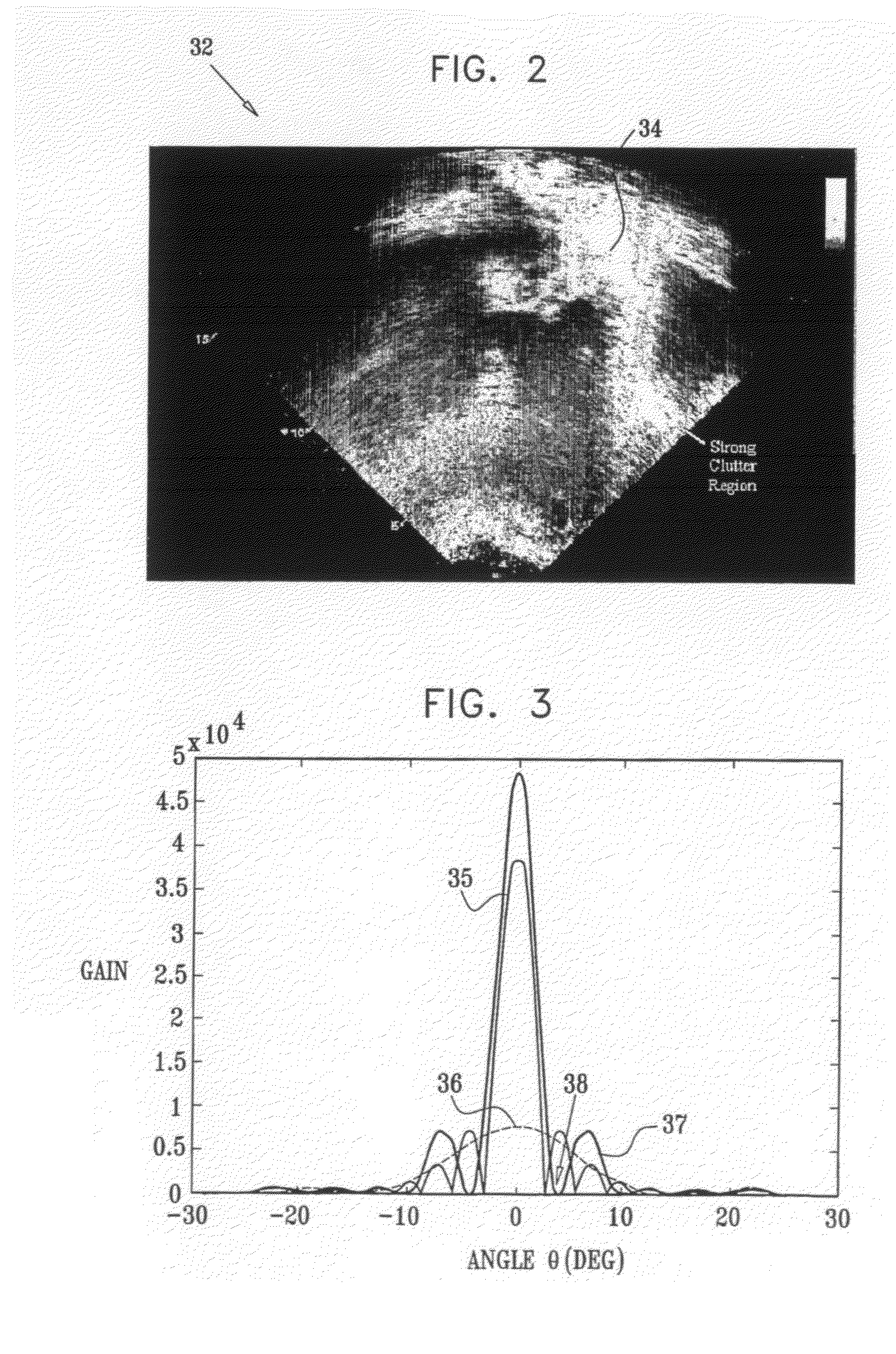
[0057]FIG. 2 is an ultrasonic image demonstrating clutter effects;

[0058]FIG. 3 is a plot that schematically shows transducer array beam patterns, in accordance with an embodiment of the present invention;

[0059]FIG. 4 is a flow chart that schematically illustrates a method for suppressing clutter effects, in accordance with an embodiment of the present invention;

[0060]FIGS. 5-6 are plots that schematically show the two-way azimuth and elevation beam patterns of the transducer used in our simulations, in accordance with an embodiment of the present invention;

[0061]FIG. 7 describes a simulated scenario, used for visual demonstration of a method for suppressing clutter effects, in accordance with an embodiment of the present invention;

[0...


PUM


Abstract

A method for ultrasonic imaging includes transmitting ultrasonic radiation toward a target and receiving the ultrasonic radiation reflected from a region of the target. A main reflected signal and an auxiliary reflected signal are defined. The reflected signals have different respective main and auxiliary beam patterns. A difference between the main reflected signal and the auxiliary reflected signal is taken, so as to generate an output signal containing a reduced level of clutter in comparison with the main reflected signal.

Description

[0001]This Application is the U.S. National Stage of International Application No. PCT / IL2005 / 001383, filed 27 Dec. 2005, which in turn claims benefit of priority from U.S. Provisional Patent Application No. 60 / 640,368, filed on Dec. 30, 2004.CROSS-REFERENCE TO RELATED APPLICATIONS[0002]This application is related to U.S. Provisional Patent Application 60 / 534,390, filed Jan. 7, 2004, whose disclosure is incorporated herein by reference.FIELD OF THE INVENTION[0003]The present invention relates generally to medical imaging systems, and particularly to methods and systems for suppressing clutter effects in ultrasonic imaging systems.BACKGROUND OF THE INVENTION[0004]Ultrasonic medical imaging plays a crucial role in modern medicine, gradually becoming more and more important as new developments enter the market. One of the most common imaging applications is echocardiography, or ultrasonic imaging of the cardiac system, providing essential anatomic and functional information on-line. Ul...

Claims


Application Information

Patent Timeline
Patent Type & Authority Patents(United States)
IPC IPC(8): G06K9/00
CPCG01S7/52026G01S7/52047A61B8/14G01S15/8993G01S7/52077
Inventor ZWIRN, GIL
Owner CRYSTALVIEW MEDICAL IMAGING
Why Eureka
Try Eureka