
Patient support usable with bariatric patients

Active Publication Date: 2016-07-07
STRYKER CORP
View PDF4 Cites 82 Cited by
  • Summary
  • Abstract
  • Description
  • Claims
  • Application Information

AI Technical Summary

Benefits of technology

The patent describes a patient support with telescoping leg assemblies. These assemblies have a variable speed control mechanism to compensate for non-linear relationships between the speed at which the upper leg moves and the speed of the lift actuator. This mechanism includes a cam arm and a cam track mounted on the lower leg, which can vary the speed at which the upper leg moves as the lift actuator raises and lowers the upper leg. The technical effect of this invention is improved stability and efficiency of patient support systems.

Problems solved by technology

For bariatric patients, i.e. morbidly obese patients having extremely large sizes and whose weights can be as high as 1000 pounds or greater, normal hospital beds are generally too small and lack sufficient structural strength to withstand the load of a bariatric patient.
Special bariatric beds have been designed to accommodate bariatric patients, but these beds generally lack the functionalities of regular hospital bed.
Further, bariatric beds are generally specialized only for bariatric patients, limiting their use for general patient care, which ultimately increases hospital costs to have such bariatric beds in stock without seeing regular usage.

Method used


Image

  • Patient support usable with bariatric patients
  • Patient support usable with bariatric patients
  • Patient support usable with bariatric patients

Examples


first embodiment

[0235]FIG. 36A, FIG. 36B, FIG. 37A, FIG. 37B, FIG. 37C and FIG. 37D depict perspective views of an extendible footboard. Extendible footboard 2120 may comprise mounting posts 2121 mounted on a footboard mounting bracket 2123 of the patient support. Each mounting post 2121 may comprise a lower half, which may be mounted on the patient support, and an upper half 2122, which may be secured to footboard panel 2124. The upper and lower halves of the mounting posts may be separate pieces linked together by linkage arms 2125, 2126. The lower halves of the mounting posts 2121 may be supported by a transverse support plate 2154 in order to keep the mounting posts 2121 aligned with receiving apertures 2155 in the footboard mounting bracket 2123. First linkage arms 2125 may be pivotally mounted on the upper halves 2122 of the mounting posts. Second linkage arms 2126 may be pivotally mounted on the lower halves of the mounting posts 2121. Pivotal mounting of the linkage arms to the mounting pos...

second embodiment

[0238]FIG. 38A, FIG. 38B, FIG. 38C, FIG. 39A, FIG. 39B and FIG. 39C depict an extendible footboard. Extendible footboard 2140 may comprise footboard mounting bracket 2143 and footboard panel 2144. The footboard mounting bracket 2143 may be mounted on a footboard insert (not shown) of the patient support. The footboard panel 2144 may be linked to the footboard mounting bracket 2143 by pivoting linkage arms 2145, 2146, 2147. First linkage arms 2145 may be pivotally connected to panel mounting posts 2142 secured to the footboard panel 2144 and to central mounting posts 2148 external to and between the footboard mounting bracket2143 and footboard panel 2144. Second linkage arms 2146 may be pivotally connected to the footboard mounting posts 2141 secured inside the footboard mounting bracket 2143 and to the central mounting posts 2148. Third linkage arms 2147 may be pivotally connected to indexable mounting posts 2149 inside the footboard mounting bracket 2143 and to the central mounting...


PUM


Abstract

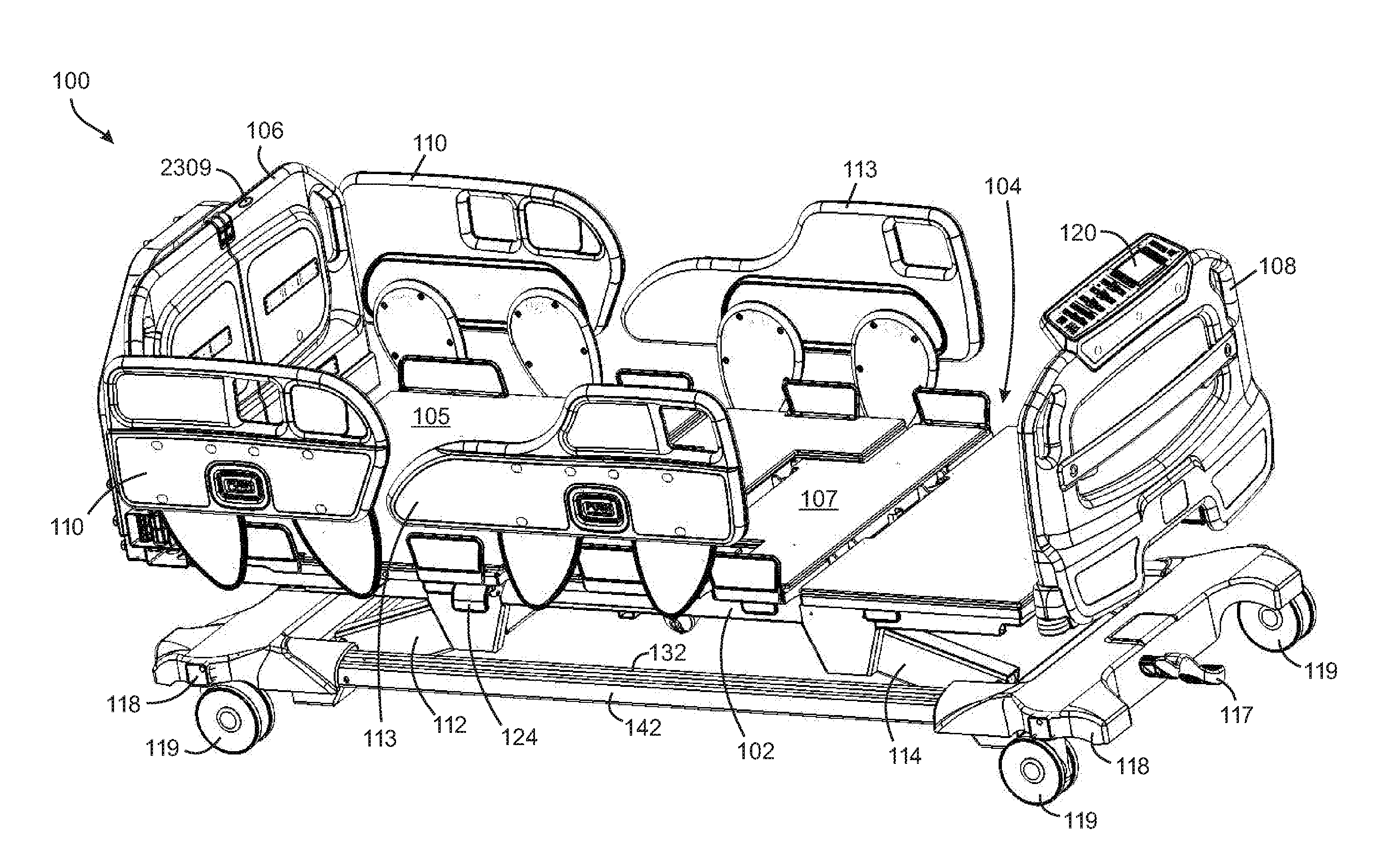
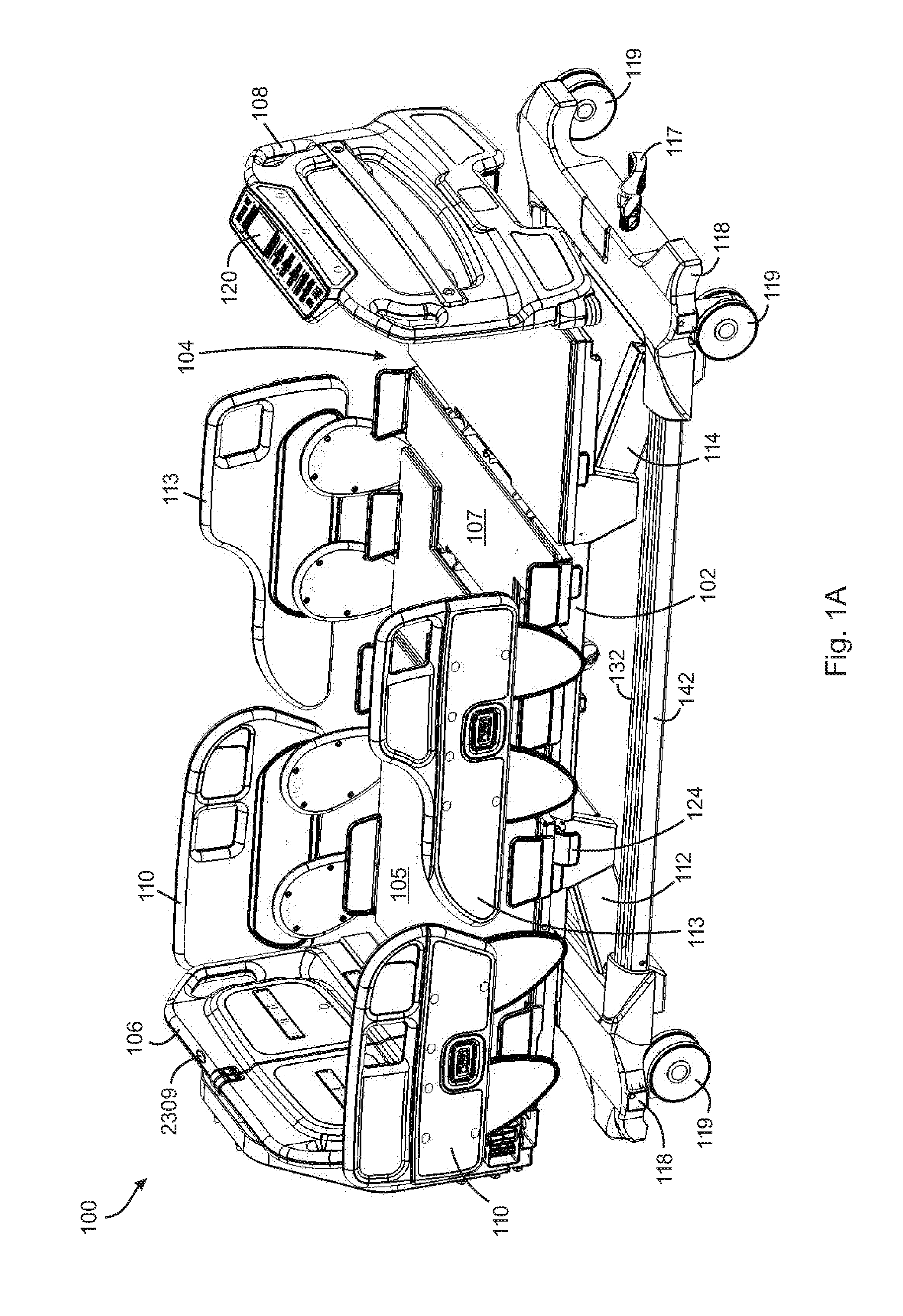
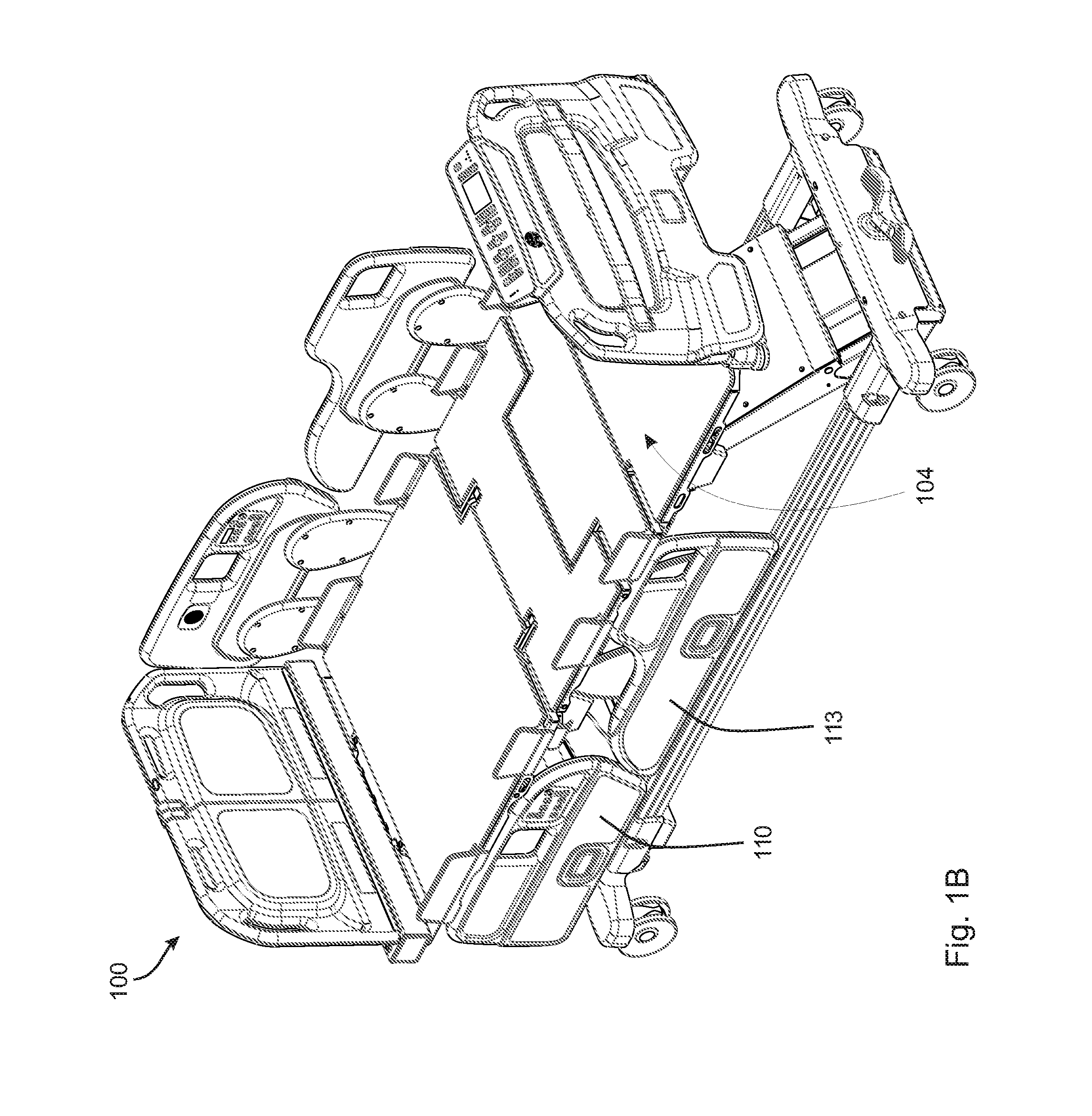
There is provided a patient support that may be adjustable in height, width, length or a combination thereof. The patient support may be useable with normal sized patients or with bariatric patients. The patient support has a variety of features to enhance operability and / or functionality, including a width adjustable caster frame, width adjustable deck portions, a width adjustable headboard and an extendible foot board to provide extra length. An enhanced lift mechanism can accommodate bariatric patients and alternative functionality in achieving deck positions improves patient comfort. Various parts of the patient support including deck panels and the footboard may be removed and replaced with ease without complicated connectors.

Description

[0001]This application claims the benefit of U.S. Provisional Pat. Application Ser. No. 61 / 874,959, filed Sep. 6, 2013, by Richard Roussy, entitled PATIENT SUPPORT USABLE WITH BARIATRIC PATIENTS, and is a national stage application of PCT / CA2014 / 050850, filed on Sep. 8, 2014, by Richard Roussy, entitled PATIENT SUPPORT USABLE WITH BARIATRIC PATIENTS, and which are incorporated herein by reference in their entireties and are commonly owned by Stryker Corporation of Kalamazoo, Mich.TECHNICAL FIELD[0002]This disclosure relates to patient supports, such as hospital beds, and more specifically, patient supports for bariatric patients. More particularly, this disclosure relates to patient supports with features for use with morbidly overweight patients.BACKGROUND[0003]Typical hospital beds are designed with numerous functionalities to facilitate patient comfort and safety and to facilitate the ability of caregivers to provide efficient and effective care. However, most hospital beds are d...

Claims


Application Information

Patent Timeline
IPC IPC(8): A61G7/012A61G7/05A61G7/018A61G7/015
CPCA61G7/012A61G7/015A61G7/0506A61G2200/16A61G7/018A61G2007/0512A61G2007/0516A61G7/0507A61G7/002A61G2203/74A61G7/0509A61G7/0512A61G7/0514A61G7/0516A61G7/0518A61G7/0524A61G7/0528A61G7/05A61G7/075A47C19/022A47C19/04
Inventor ROUSSY, RICHARD BRIANCONNELL, JASON JOHNELKU, JOSEPH STEVEN DAVIDCERNY, JASON JAMESGEORGE, CHRISTOPHER ALANROUSSY, JOSEPH WILLIAMJACOB, CHRISTOPHER SCOTTYUSUF, ALEEM
Owner STRYKER CORP
Learn More