Composting device
a technology of composting device and slurry, which is applied in the direction of gas current separation, grain treatment, products, etc., can solve the problem of not being able to produce compost in a continuous way
- Summary
- Abstract
- Description
- Claims
- Application Information
AI Technical Summary
Benefits of technology
Problems solved by technology
Method used
Image

Examples
first embodiment
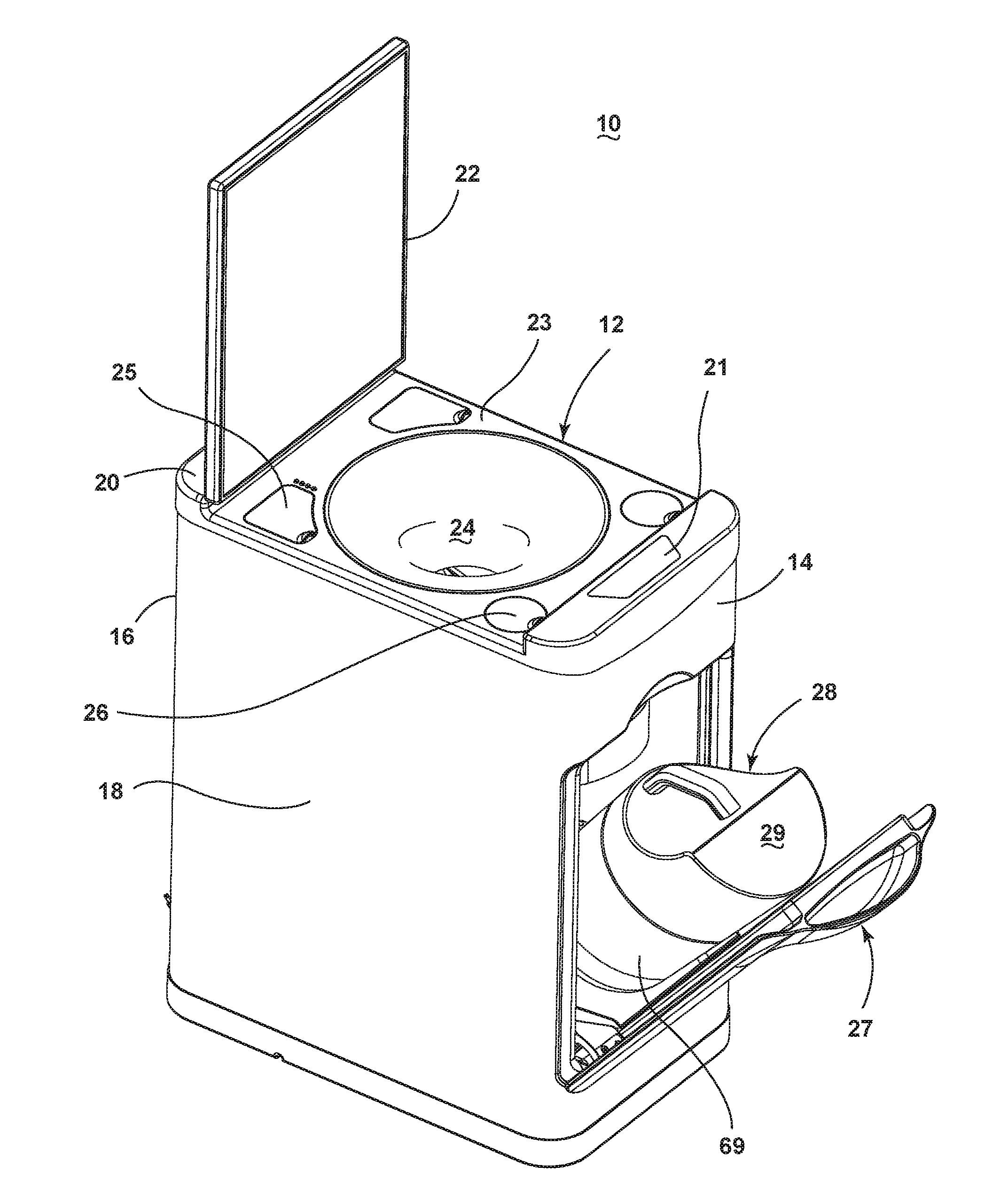
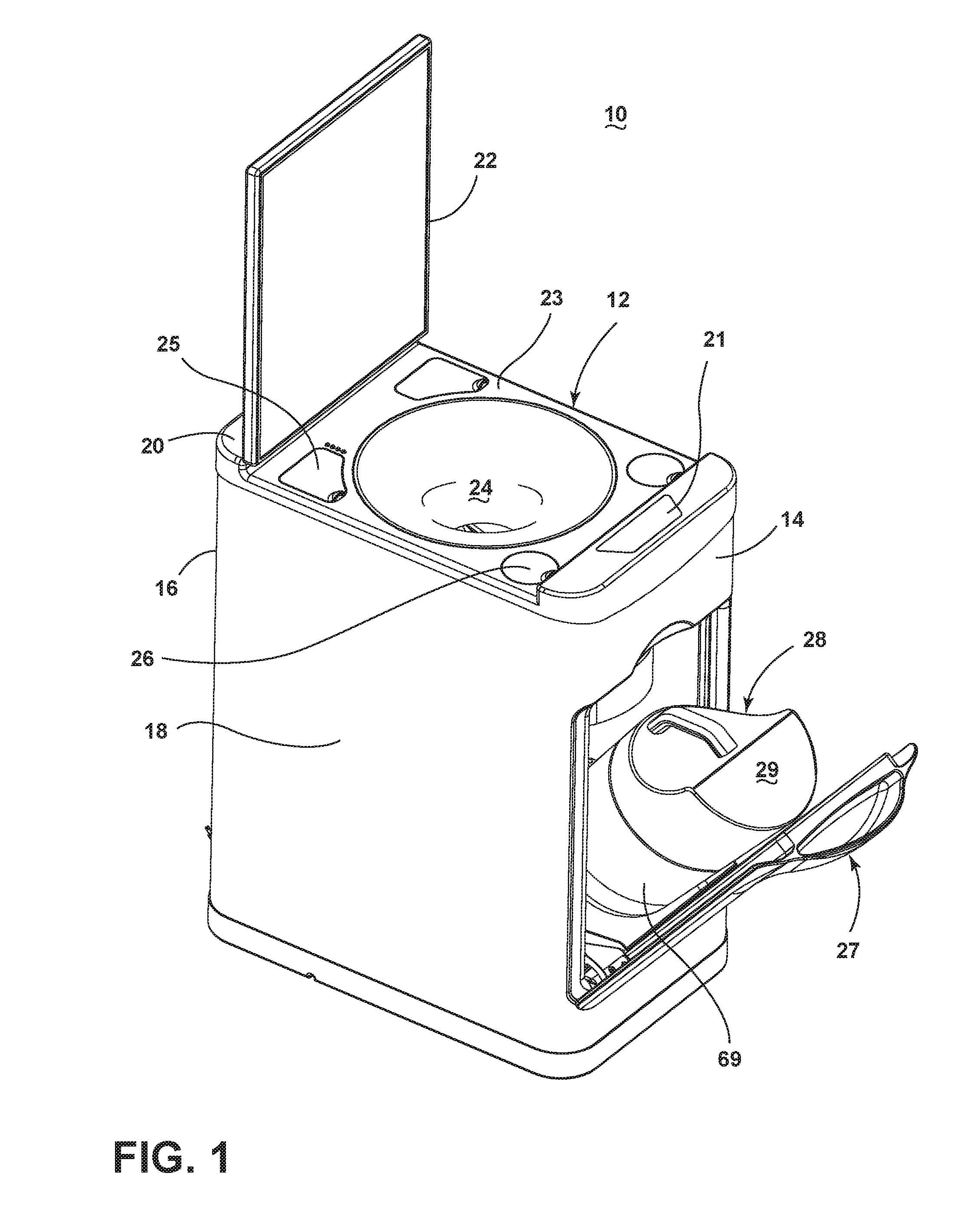
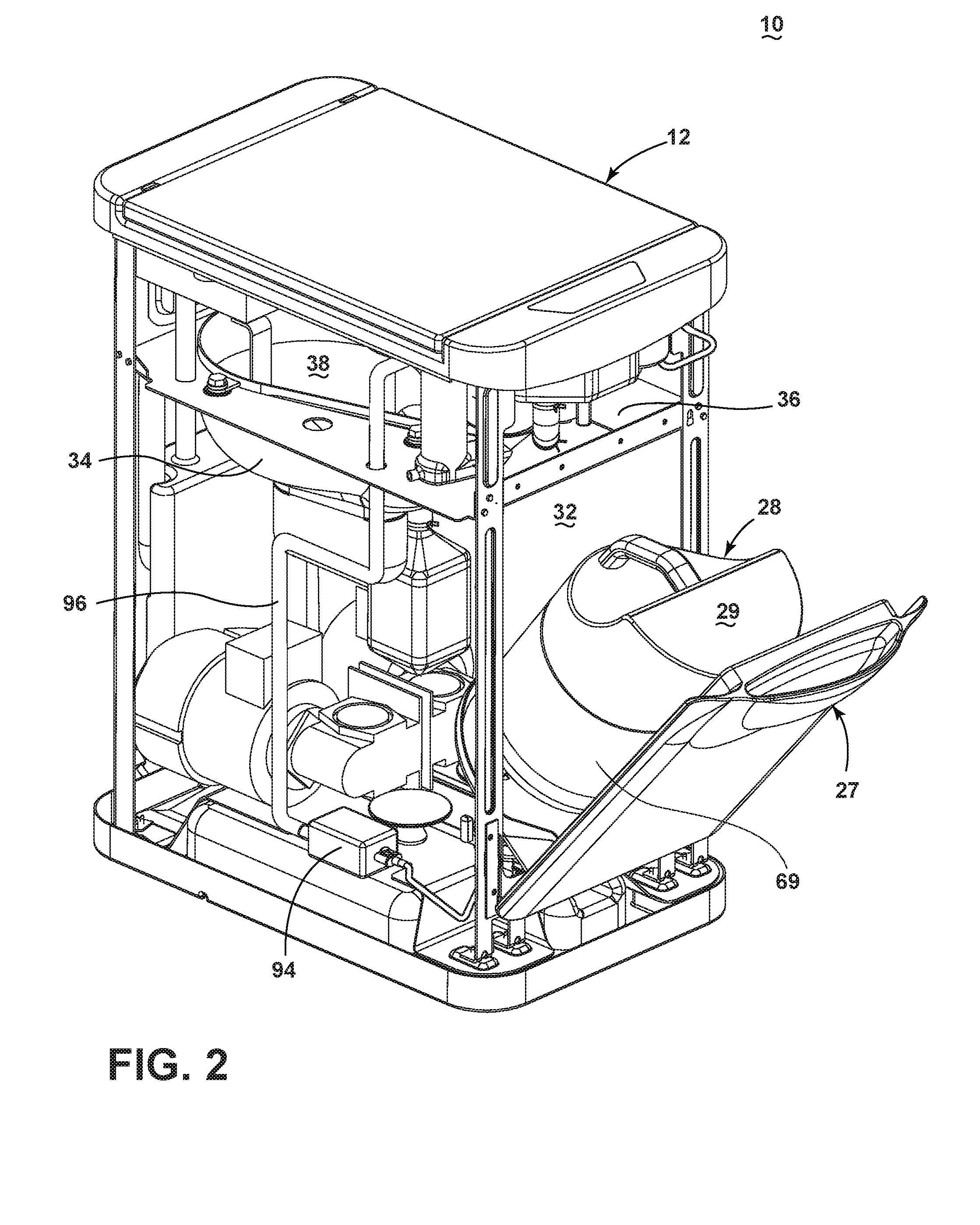
[0031]FIG. 1 illustrates a perspective view of a device 10 in the form of a composter for transforming refuse into compost according to the invention. The composting device 10 may include a cabinet 12 having a front wall 14 spaced from a back wall 16, and a pair of side walls 18 extending between the front and back walls 14, 16.
[0032]A top wall 20 may enclose the cabinet 12 at the top of the front wall 14, back wall 16, and the pair of side walls 18. The top wall 20 may include a cover 22 pivotally mounted to a portion of the top wall 20 for movement between open or closed positions, and to enable access to other components of the cabinet 12. In other embodiments, the cover 20 is slidably mounted or removably mounted to a top portion of the top wall 20. The top wall 20, as well as the remainder of the cabinet 12, may be formed of a rigid and durable material such as steel, a metal alloy, or a hardened polymer composite material.
[0033]A controller (not shown) may be located within th...
second embodiment
[0066]FIG. 9 is a perspective view of the composting device according to the invention, where each of the auger and the reducing mechanisms for the hopper and the container is provided with a motor for independent operation. The composting device illustrated in FIG. 9 may otherwise be similar to the composting device 10 described above in having a hopper 124, a container 126 for transforming the refuse into compost by decomposing the refuse received in the hopper 124, and transferring the refuse into the container 126 for additional composting.
[0067]The primary difference between the first embodiment of the composting device 10 described above and the device in FIG. 9 may be the number of motors. As illustrated in FIG. 9, the hopper 124 and the container 126 are provided with motors 132, 134 which are dedicated for the operation of the hopper 124 and the container 126, respectively. The hopper 124 may be operably coupled to a motor 132, and the container 126 may be coupled to a moto...
PUM
| Property | Measurement | Unit |
|---|---|---|
| time | aaaaa | aaaaa |
| time | aaaaa | aaaaa |
| volume | aaaaa | aaaaa |
Abstract
Description
Claims
Application Information
 - R&D
- Intellectual Property
- Life Sciences
- Materials
- Tech Scout
- Unparalleled Data Quality
- Higher Quality Content
- 60% Fewer Hallucinations
Browse by: Latest US Patents, China's latest patents, Technical Efficacy Thesaurus, Application Domain, Technology Topic, Popular Technical Reports.
© 2025 PatSnap. All rights reserved.Legal|Privacy policy|Modern Slavery Act Transparency Statement|Sitemap|About US| Contact US: help@patsnap.com