
Spool switching valve device

Active Publication Date: 2016-07-21
NIDEC TOSOK CORP
View PDF24 Cites 2 Cited by
  • Summary
  • Abstract
  • Description
  • Claims
  • Application Information

AI Technical Summary

Benefits of technology

The spool switching valve device described in this patent has a cylindrical housing with empty cavities drilled towards the center from both ends. The valve bodies are spherical and fit into these cavities. The device has several components including input ports, valve body movable portions, valve seat portions, and valve seat mounting portions. These components work together to open and close paths for fluid communication. The device can switch between different input ports and has the advantage of being easily mounted and detached. Overall, the spool switching valve device is designed for efficient and reliable fluid control.

Problems solved by technology

For this reason, it is required for a worker or others to be skilled for the assembly work, so that there may be a problem in workability.

Method used


Image

  • Spool switching valve device
  • Spool switching valve device
  • Spool switching valve device

Examples


Embodiment Construction

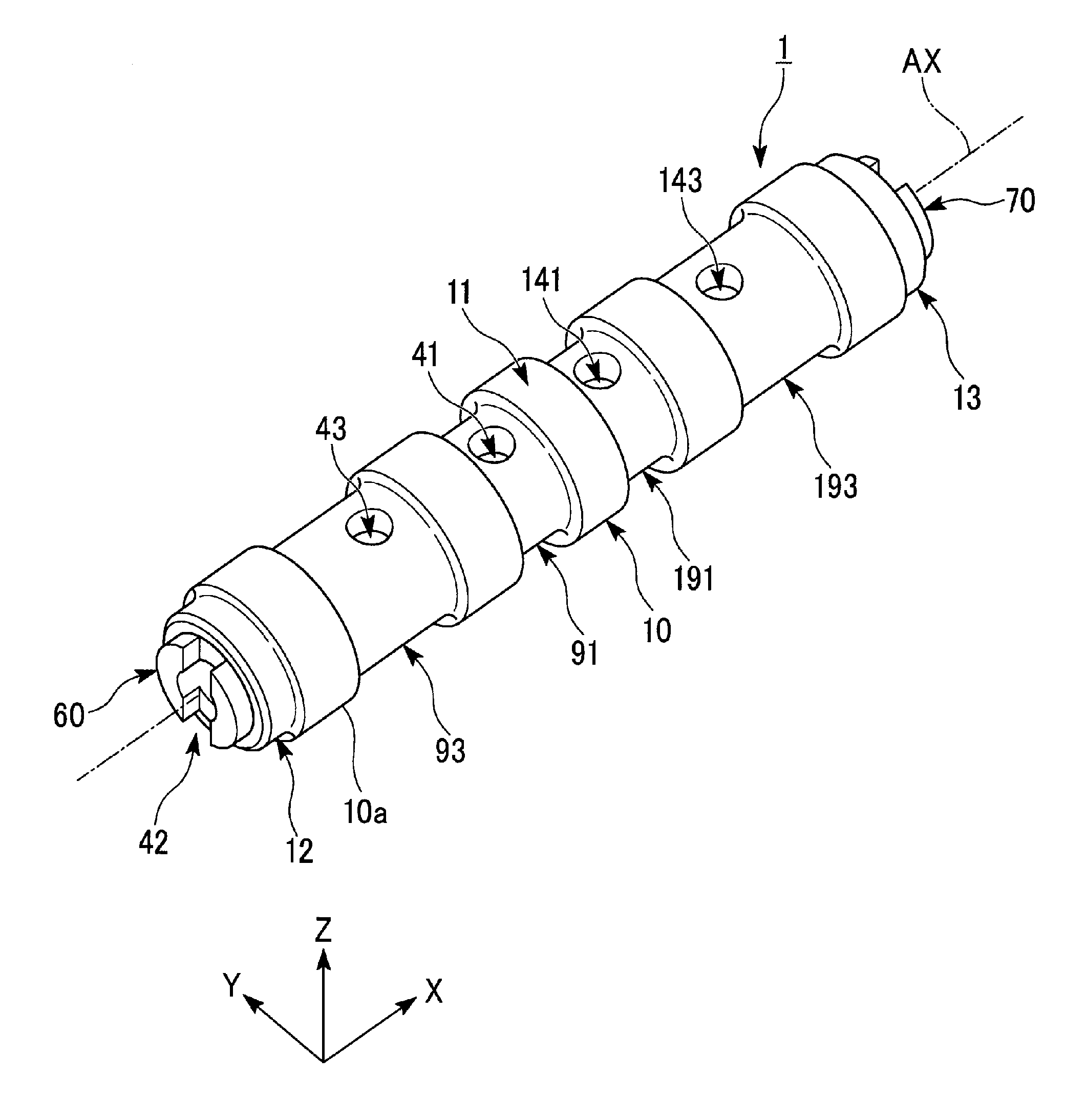
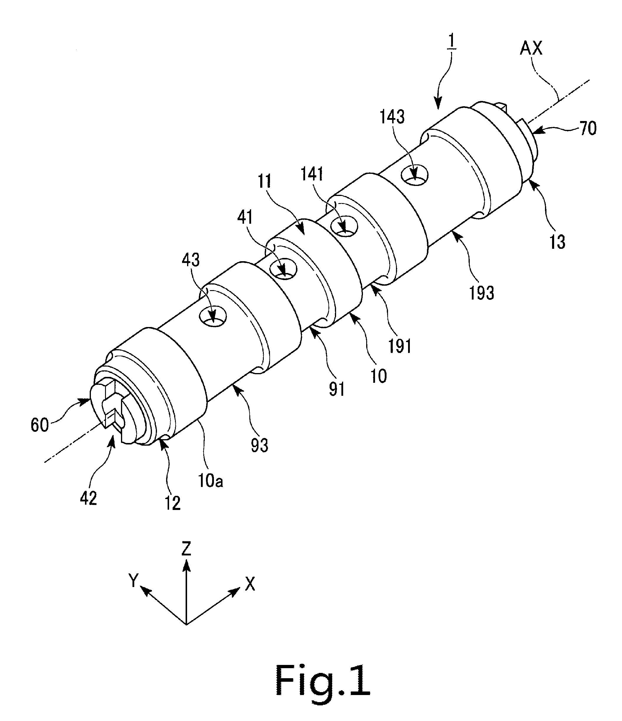
[0014]Hereinafter, a spool switching valve device according to a preferred embodiment of the present disclosure will be described with reference to FIG. 1 to FIG. 6. FIG. 1 is of an external perspective view of a spool switching valve device 1.

[0015]In the drawings, an X-Y-Z coordinate system is provided as an appropriate three-dimensional orthogonal coordinate system. An X-axis direction is a length direction of the cylindrical shaped spool switching valve device 1 shown in FIG. 1 and is parallel to an axial AX direction along a direction in which hollow cavities 20 and 30, which will be described in more detail in a subsequent section, extend. A Z-axis direction is a direction in which first input ports 41 and 141, second input ports 42 and 142, and output ports 43 and 143, which will be described in more detail in a subsequent section, extend centered at an axis AX. A Y-axis direction is a direction orthogonal to the Z-axis direction and the Y-axis direction.

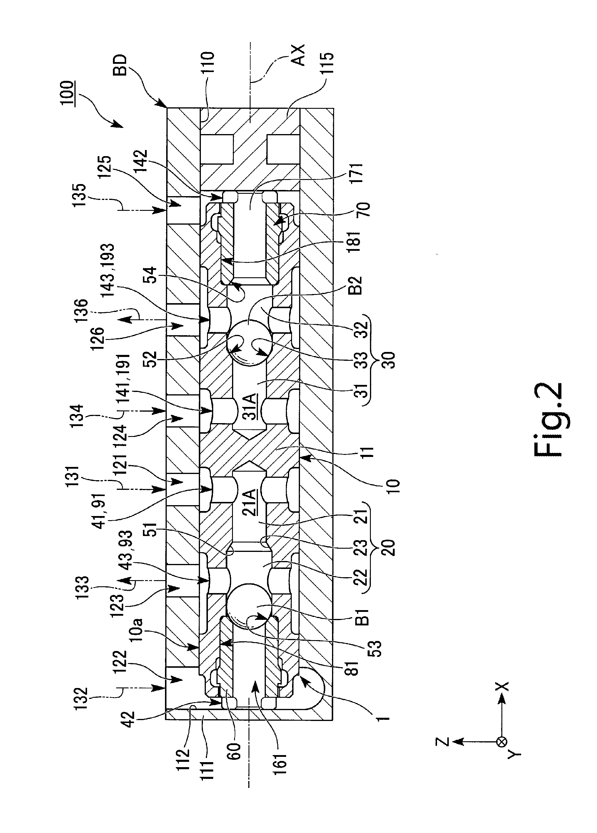
[0016]FIG. 2 is a cro...


PUM


Abstract

A spool switching valve device may include a columnar spool housing and spherical valve bodies. The spool housing includes first input port cavity portions, valve body movable portions and valve seat members. Each valve seat member has a through hole and includes a second input port portion. A second valve seat portion is provided to open and close the gap between valve body movable portion and the second input port portion. Each valve body movable portion includes an output port penetrating the side surface of the spool housing to communicate with the outside of the spool. Each valve seat mounting portion includes an engagement receiving portion suppressing the detachment of the valve seat members when the valve seat member is actually mounted. Each valve seat member includes an engagement portion fitted into the engagement receiving portion when the valve seat member is mounted to the valve seat mounting portion.

Description

CROSS REFERENCE TO RELATED APPLICATION[0001]The present invention claims priority under 35 U.S.C. §119 to Japanese Application No. 2015-007899 filed Jan. 19, 2015, the entire content of which is incorporated herein by reference.FIELD OF THE DISCLOSURE[0002]The present disclosure relates to a spool switching valve device.DESCRIPTION OF THE RELATED ART[0003]In an automatic transmission or other elements of a car, provided is a switching structure of hydraulic circuits (for example, Japanese Patent Application Laid-open Publication No. S63-038775). In the switching structure described in the publication, a structure formed of one output port per two input ports is provided as a set, and one longitudinal side thereof is provided to a bottomed cylindrically shaped housing. Inside the housing, a pair of pistons at one end and the other end and an accommodation portion are provided. The pair of pistons includes a pair of valve bodies at the one end and the other end and a pair of valve sea...

Claims


Application Information

Patent Timeline
IPC IPC(8): F16K11/07
CPCF16K11/0716F16K15/042Y10T137/2569Y10T137/2567Y10T137/2564F16K11/056F16K11/105
Inventor YAMAKI, YOSHINORIOOHARA, KENJIKONAGAYA, YASUAKI
Owner NIDEC TOSOK CORP
Features
  • Generate Ideas
  • Intellectual Property
  • Life Sciences
  • Materials
  • Tech Scout
  • Unparalleled Data Quality
  • Higher Quality Content
  • 60% Fewer Hallucinations
Learn More