

Endoscope cleaning tube
a technology for cleaning tubes and endoscopes, applied in endoscopes, medical science, diagnostics, etc., can solve the problems of affecting the cleaning and disinfection of endoscopes, and the inability to supply a sufficient amount of fluid into the conduits
- Summary
- Abstract
- Description
- Claims
- Application Information
AI Technical Summary
Benefits of technology
Problems solved by technology
Method used
Image

Examples
first embodiment
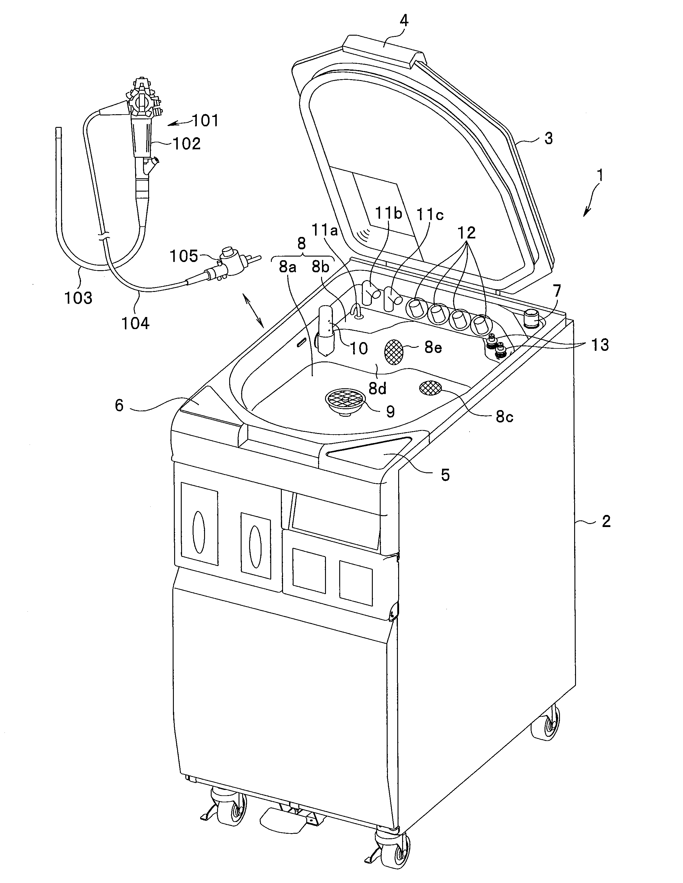
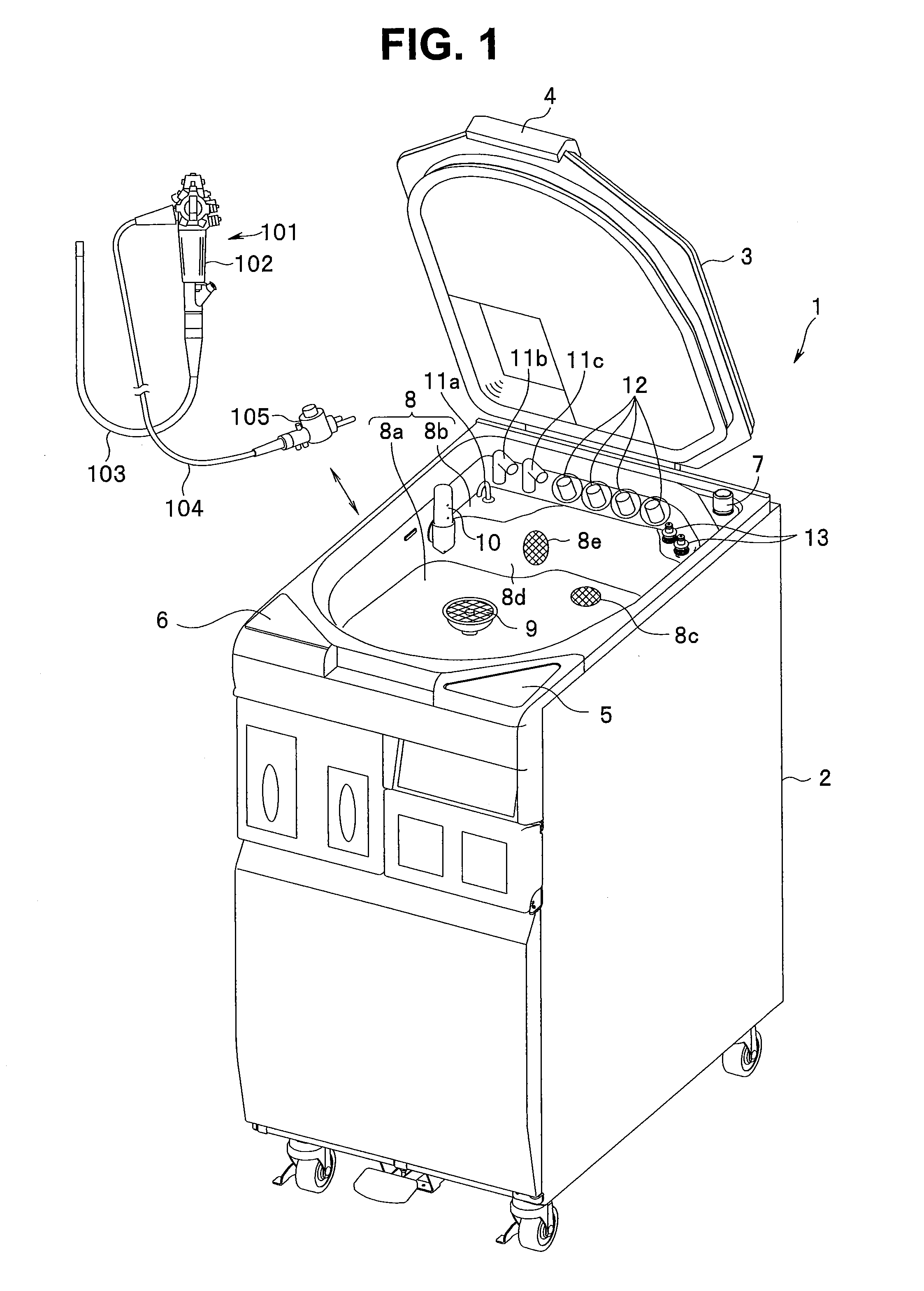
[0032]A first embodiment of the present invention is shown in FIG. 1 to FIG. 9. As shown in FIG. 1, an endoscope reprocessing apparatus 1 is intended to perform a reprocess to allow an endoscope 101 after use to be inserted into a subject again. The reprocess as referred to herein can be selected appropriately depending on a contaminated state of the endoscope and a site into which the endoscope 101 is inserted. For example, at least one of cleaning, disinfection, and sterilization can be selected, where the cleaning is used to remove contaminants such as protein, disinfection is used to neutralize harmful bacteria and viruses, and sterilization is used to kill bacteria and viruses.
[0033]Principal part of the endoscope reprocessing apparatus 1 is made up of an apparatus body 2, a processing tank 8 provided in the apparatus body 2, and a top cover 3 adapted to open and close the processing tank 8.
[0034]With rear part of the top cover 3 pivotably supported, front part of the top cover...
second embodiment
[0072]A second embodiment of the present invention is shown in FIG. 10 to FIG. 12. With the cleaning tube 31 according to the first embodiment described above, for example, if the endoscope-side connector portion 34 comes off the pipe sleeve 106 during a reprocessing step, the fluid flowing through the circulation conduit 21 is not restricted, and thus it is not possible to detect the detachment of the endoscope-side connector portion 34 based on the flow rate measured by the flow sensor 23.
[0073]In contrast, according to the present embodiment, if the endoscope-side connector portion 34 comes off the pipe sleeve 106, the pressure-receiving portion 43 provided in the endoscope-side connector portion 34 blocks up the fluid introduction port 35a, making it possible to detect the detachment of the endoscope-side connector portion 34 based on the flow rate measured by the flow sensor 23. Note that components having the same functions as those in the first embodiment are denoted by the s...
third embodiment
[0089]A third embodiment of the present invention is shown in FIG. 13 to FIG. 20. According to the present embodiment, a cam link mechanism 41C is disposed in the endoscope-side connector portion 34, being configured to form or block a gap between the cam link mechanism 41C and pipe sleeve 106. Note that components having the same functions as those in the first embodiment are denoted by the same reference numerals as the corresponding components in the first embodiment, and detailed description thereof will be omitted.
[0090]That is, as shown in FIG. 15, the cam link mechanism 41C provided in the housing portion 35 has a cylindrical movable portion 61 in lower part, convex guide portions 61a are formed at symmetrical positions on an outer circumference of the cylindrical movable portion 61, extending in the up-and-down direction, and cam slots 61b are formed at opposite positions on the outer circumference. Furthermore, a cam pin 63 provided at a lower end of a rotating shaft 62 is ...
PUM
 Abstract
Description
Claims
Application Information