Electromagnetic-wave transmitting cover
Active Publication Date: 2016-08-25
TOYODA GOSEI CO LTD
2 Cites 18 Cited by
AI-Extracted Technical Summary
Problems solved by technology
Thus, the front grille interferes with a pathway of a radio wave (for example, a millimeter wave).
However, the electromagnetic-wave transmitting cover refers to only attenuation of a millimeter wave, and can disadvantageously cope with an increase...
Benefits of technology
[0023]In the electromagnetic-wave transmitting cover according to the present invention, the distance between the two base materials is 0.12 mm or less to suppress a deviation in angle from increasing so as to achieve a deviation in angle of 0.3° or less. More specifically, range extension of an electromagnetic wave (for example, a sensing radar) transmitted through the electromagnetic-wave transmitting cover can be achieved.
[0024]As described above, the electromagnetic-wave transmitting cover according to the present invention can achieve range extension and angle widening of a sensing radar to obtain an electromagnetic-wave transmitting cover which is excellent in design property.
[0025]In the electromagnetic-wave transmitting cover according to the present invention, a difference obtained by subtracting the relative permittivities of the base material and the translucent base material from the rela...
Abstract
To provide an electromagnetic-wave transmitting cover which can achieve range extension and angle widening of a sensing radar and is excellent in design property. An electromagnetic-wave transmitting cover of the invention includes a base material made of an electromagnetic-wave-transmissive material, a light-transmitting base material formed on a surface of the base material and made of a light-transmissive material, and a design layer disposed between the base material and the light-transmitting base material, the electromagnetic-wave transmitting cover transmitting an electromagnetic wave, the electromagnetic-wave transmitting cover has an electromagnetic-wave transmitting area which transmits the electromagnetic wave, the base material and the light-transmitting base material in the electromagnetic-wave transmitting area has an interval of 0.12 mm or less, an adhesive layer is formed on an entire surface between the base materials, and a deviation in angle when the electromagnetic wave is transmitted is 0.3° or less.
Application Domain
Radiating element housingsAntenna equipments with additional functions +1
Technology Topic
EngineeringRadar +1
Image
Examples
- Experimental program(1)
Example
[0038]The present invention will be described in detail below with reference to an embodiment.
Embodiment
[0039]As an embodiment of the present invention, a cover of a millimeter-wave radar for vehicle is formed. In the embodiment, an example in which a cover of a millimeter-wave radar disposed on a vehicle grille is applied as an electromagnetic-wave transmitting cover is given. However, the present invention is not limited to the embodiment.
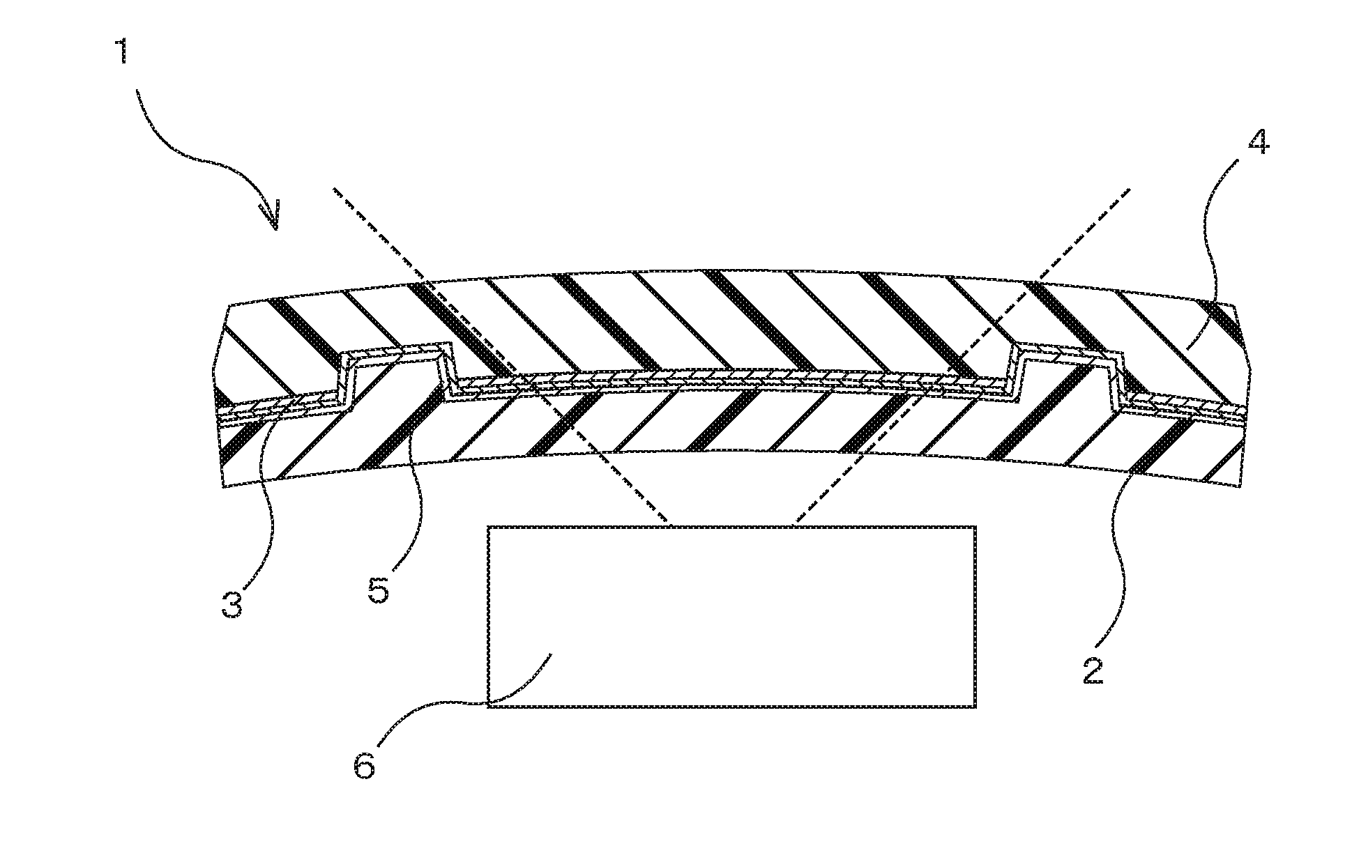
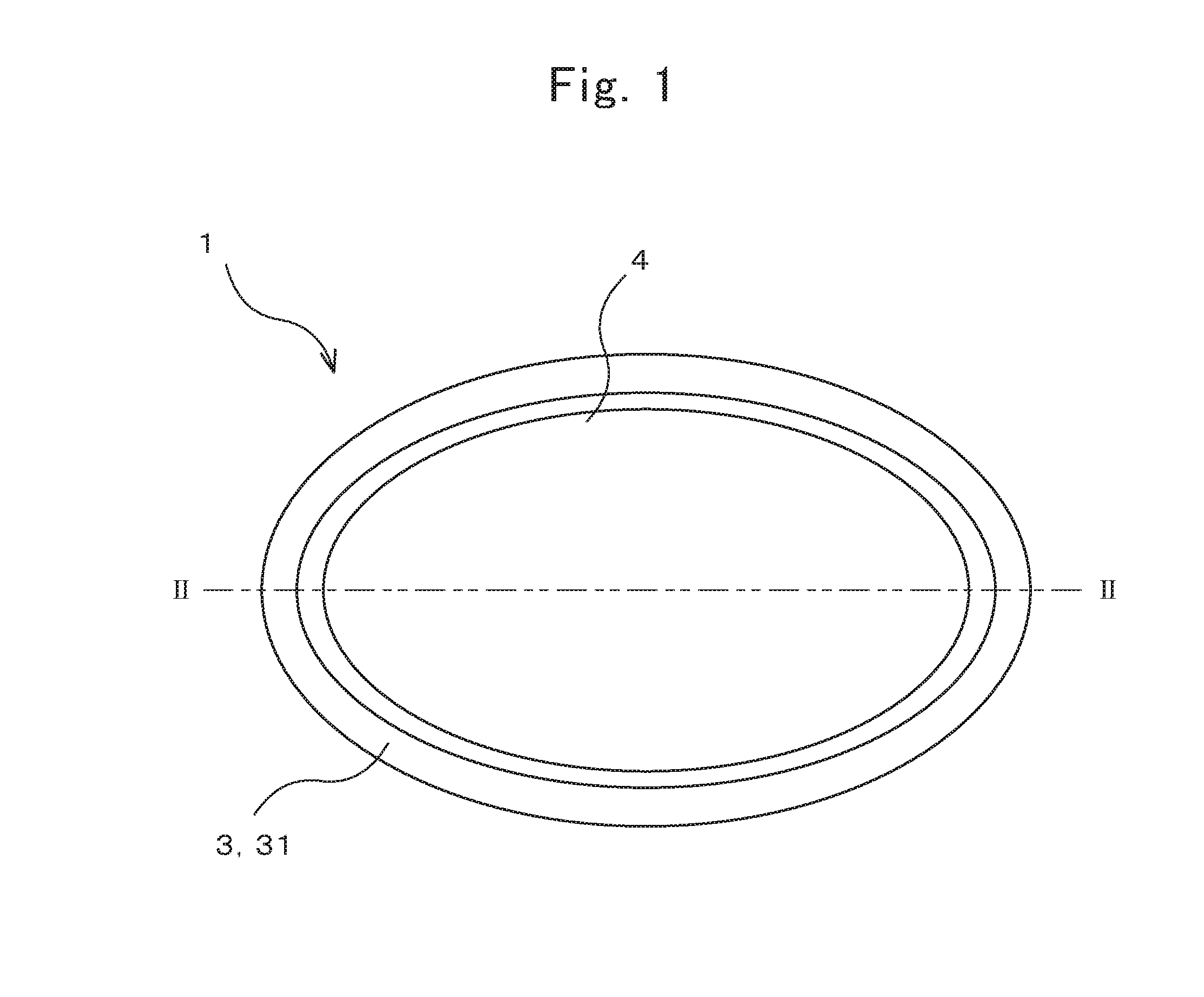
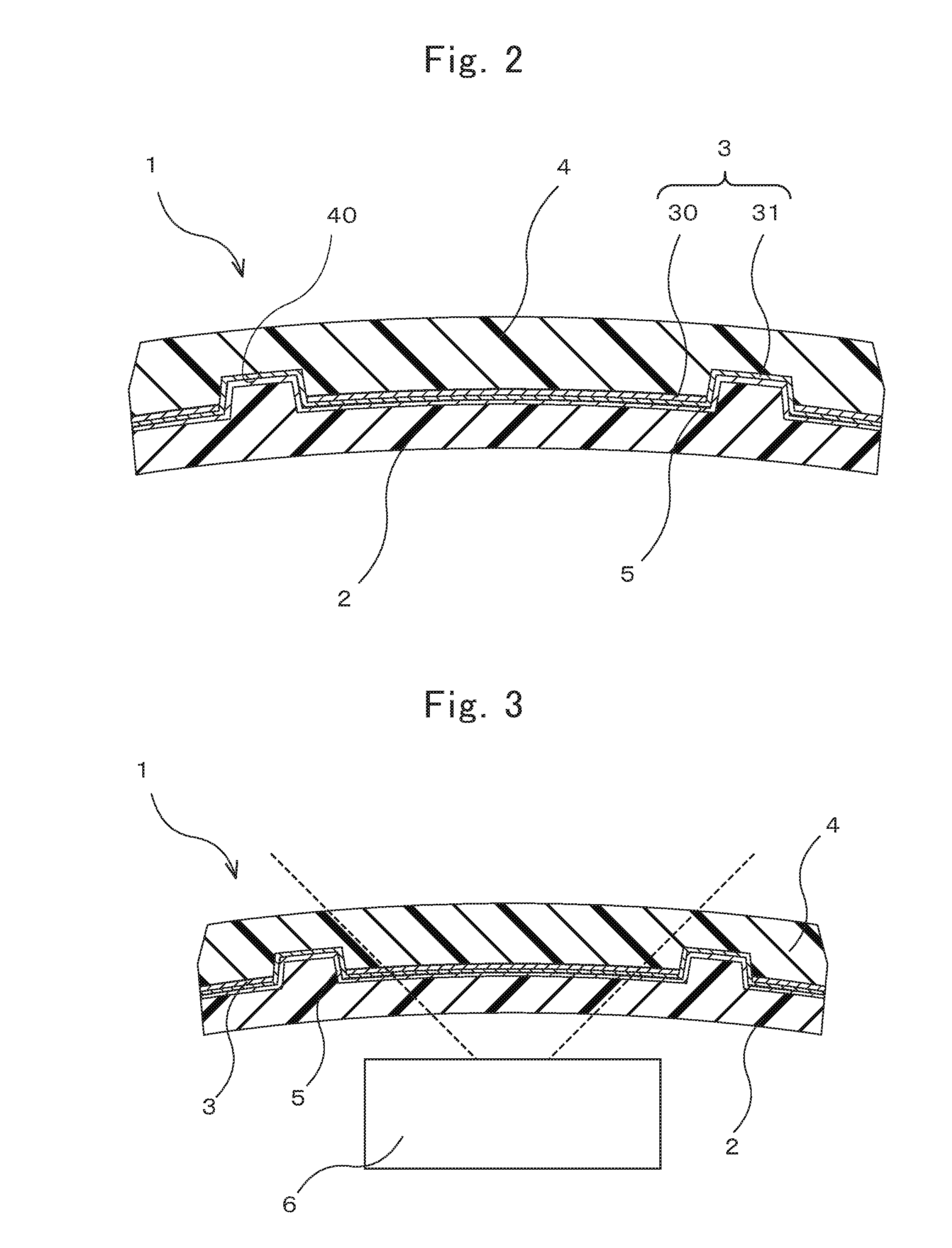
[0040]FIG. 1 shows a front view of a configuration of an electromagnetic-wave transmitting cover 1 according to the embodiment, and FIG. 2 shows a sectional view along a II to II line in FIG. 1. FIG. 3 shows a relationship between the electromagnetic-wave transmitting cover 1 and a millimeter-wave radar device 6 when the electromagnetic-wave transmitting cover 1 is used in a millimeter-wave radar.
[0041]Electromagnetic-Wave Transmitting Cover
[0042]The electromagnetic-wave transmitting cover 1 according to the embodiment, as shown in FIGS. 1 and 2, has a plate-like shape having a substantially elliptical outer shape. The electromagnetic-wave transmitting cover 1 has a base material 2, a design layer 3, a light-transmitting base material 4, and an adhesive layer 5. The electromagnetic-wave transmitting cover 1 according to the embodiment, as shown in FIG. 3, is disposed in front of (i.e., a transmission direction of a millimeter wave) the millimeter-wave radar device 6.
[0043]Base Material
[0044]The base material 2 is located on the rear side of the electromagnetic-wave transmitting cover 1, and the design layer 3 and the light-transmitting base material 4 are located in front of the electromagnetic-wave transmitting cover 1. The base material 2 is made of a material through which an electromagnetic wave can be transmitted. Since the base material 2 is made of the material through which an electromagnetic wave can be transmitted, the cover can transmit the electromagnetic wave (i.e., a millimeter wave) to cause the radar to function as a millimeter-wave radar.
[0045]The base material 2, as shown in FIGS. 1 and 2, has a plate-like shape having a substantially elliptical outer shape matched with the outer shape of the electromagnetic-wave transmitting cover 1. A surface (front surface) of the base material 2 on the front side has an uneven shape corresponding to the design expression (more specifically, a groove portion 40 (to be described later) of the design layer 3.
[0046]Examples of a material of which the base material 2 is made and through which an electromagnetic wave is transmitted include, but are not limited to, resins such as a polycarbonate resin, an acrylic resin, an AES resin, and an ABS resin.
[0047]The base material 2 may have a latching means to attach the electromagnetic-wave transmitting cover 1 to the vehicle. The base material 2 preferably has a positioning means which sets relative positions of the electromagnetic-wave transmitting cover 1 and the millimeter-wave radar device 6. The base material 2 has these means to make it possible to locate and fix the electromagnetic-wave transmitting cover 1 to the vehicle and the millimeter-wave radar device 6.
[0048]Design Layer
[0049]The design layer 3 is disposed between the base material 2 and the light-transmitting base material 4. The design layer 3 performs design expression on the electromagnetic-wave transmitting cover 1.
[0050]The design layer 3 may be formed by depositing a metal material such as indium on the base material 2 or the light-transmitting base material 4, or may be printed and formed on the base material 2 or the light-transmitting base material 4 by screen printing or the like. Furthermore, predetermined design printed and formed on a transfer film is transferred and formed on the base material 2 or the light-transmitting base material 4. The design layer 3 obtained by depositing or printing predetermined design on a resin film may be laminated on the base material 2 or the light-transmitting base material 4. As the material of the design layer 3, a material of one type or materials of two or more types may be used. The design layer 3 may be configured by a single layer or a multilayer. For example, a layer obtained by bonding small pieces of film on which a second design is deposited and formed on a resin film on which a first design is printed and formed may be used as the design layer 3. Furthermore, a protecting layer may be formed on the front-surface side and/or the rear-surface side of the design layer 3.
[0051]In this embodiment, the design layer 3 is laminated and formed on the front surface (or rear surface) of the light-transmitting base material 4 on the rear side thereof. The design layer 3 has a printed portion 30 obtained by screen-printing a black paint and a deposited portion 31 obtained by depositing indium.
[0052]The printed portion 30 is printed on the rear surface of the light-transmitting base material 4. The printed portion 30 is not formed on the interior (more specifically, on an inner peripheral surface) of a groove portion 40 formed on the rear surface of the light-transmitting base material 4.
[0053]The deposited portion 31 is deposited on the rear surface of the printed portion 30 and on the interior of the groove portion 40. With the printed portion 30 and the deposited portion 31, when the electromagnetic-wave transmitting cover 1 according to the embodiment is visually checked from the front-surface side, a metal color obtained by the deposited portion 31 can be confirmed in the groove portion 40, a black color obtained by the printed portion 30 is displayed on portions except for the groove portion 40.
[0054]On the rear surface of the design layer 3, a reinforcing layer obtained by heat-dry-coating or UV-coating an acrylic resin is laminated (this configuration is not shown). This reinforcing layer is interposed between the design layer 3 and the base material 2 and between the design layer 3 and the adhesive layer 5.
[0055]Light-Transmitting Base Material
[0056]The light-transmitting base material 4 is formed on the front surface of the base material 2 and made of a light-transmissive material. The light-transmissive material means a material through which at least visible light is transmitted, and is preferably a transparent or semi-transparent resin through which the design layer 3 can be visually checked.
[0057]The light-transmitting base material 4, as shown in FIGS. 1 and 2, has a plate-like shape having an elliptical outer shape matched with the outer shape of the electromagnetic-wave transmitting cover 1. The outer peripheral shape of the light-transmitting base material 4 is matched with the outer peripheral shape of the base material 2. In the light-transmitting base material 4, as shown in FIGS. 1 and 2, the groove portion 40 concaved from the rear surface to the front side is formed. The groove portion 40 of the light-transmitting base material 4 has a shape of design expression of the design layer 3. In the embodiment, as shown in FIGS. 1 and 2, the groove portion 40 is formed in an end portion of the electromagnetic-wave transmitting cover 1.
[0058]The rear surface of the light-transmitting base material 4 has an uneven shape substantially matched with the front surface of the base material 2. More specifically, the front surface of the base material 2 is formed to have a shape (i.e., both the surfaces can be brought into tight contact with each other while being substantially matched with each other) corresponding to the groove portion 40 of the light-transmitting base material 4.
[0059]The light-transmitting base material 4 configures a front-side portion of the electromagnetic-wave transmitting cover 1 according to the embodiment. Although a light-transmissive material constituting the light-transmitting base material 4 is not limited to a specific material, a material having a high weather resistance is preferably selected. As the light-transmissive material (for example, a transparent resin material) having a high weather resistance, a resin such as a polycarbonate resin or an acrylic resin can be given.
[0060]The light-transmitting base material 4 is preferably made of a material having a relative permittivity equal to that of the base material 2. More specifically, when the base material 2 is made of an AES resin, the light-transmitting base material 4 is preferably made of polycarbonate (PC). The relative permittivity of PC and the relative permittivity of AES are each 2.7 (2.6 to 2.8) at room temperature and 76.5 GHz.
[0061]Adhesive Layer
[0062]The adhesive layer 5 is formed between the base material 2 and the light-transmitting base material 4. The adhesive layer 5 is formed between the base material 2 and the light-transmitting base material 4 to bond both the base materials 2 and 4 to each other. The adhesive layer 5 is preferably formed in an entire area between the base material 2 and the light-transmitting base material 4. The adhesive layer 5 is preferably formed between the base material 2 and the light-transmitting base material 4 without forming an air layer.
[0063]In the embodiment, the adhesive layer 5 is disposed between the design layer 3 formed integrally with the light-transmitting base material 4 and the base material 2. More specifically, when the design layer 3 is formed on at least either one of the base materials 2 and 4, the adhesive layer 5 is formed between the design layer 3 and the other one of the base materials 2 and 4.
[0064]A method of forming the adhesive layer 5 is not limited to a specific method, and, for example, a method in which, after either one of the base material 2 and the light-transmitting base material 4 is molded, the other one of the base materials 2 and 4 is insert-molded together with an adhesive agent, a method of filling and hardening an adhesive agent between the base materials 2 and 4, and the like can be given.
[0065]The adhesive agent is insert-molded together with both the base materials 2 and 4 to make it possible to uniformly wettably spread the adhesive agent with the pressure of an injected resin and to prevent air insertion. In the event that a thermosetting adhesive agent which is hardened with heat of the injected resin is used, the step of hardening the adhesive agent need not be separately performed to make it possible to suppress an increase in number of manufacturing steps.
[0066]Although the adhesive agent for forming the adhesive layer 5 is not limited to a specific adhesive agent, a material which can suppress a deviation in angle and attenuation of a millimeter wave (electromagnetic wave) when the adhesive layer 5 is formed. As the adhesive agent, an adhesive agent made of a resin such as polyester, epoxy, acrylic, urethane, polyamide, or silicone can be given. Especially, as described above, as an adhesive agent suitable for adhesion in insert molding, a resin adhesive agent such as epoxy, urethane, silicone, or nylon is given. An epoxy-resin adhesive agent which is of a thermosetting type and is not decomposed at a temperature (for example, 230° C.) of the resin is preferably used.
[0067]The epoxy-resin adhesive agent also has a low water absorption rate (or a moisture permeability) of 3.8%. For this reason, even though the adhesive layer 5 is exposed at the end portion (i.e., end face) of the electromagnetic-wave transmitting cover 1, moisture can be suppressed from being inserted between both the base materials 2 and 4 to suppress design property from being deteriorated.
[0068]As the adhesive agent for forming the adhesive layer 5, due to its workability, a liquid adhesive agent in a state in which the adhesive agent can be applied to at least either one of the base material 2 and the light-transmitting base material 4 is preferably used. A solution-type adhesive agent (solvent-type adhesive agent) is more preferably used. Since the solvent-type adhesive agent is of a coating type, the adhesive agent preferably has a viscosity of 500 mPa or less (i.e., a low-viscosity adhesive agent) is preferably used.
[0069]The low-viscosity adhesive agent flows between the front surface of the base material 2 and the rear surface of the light-transmitting base material 4 to fill the space. More specifically, even though the front surface of the base material 2 and the rear surface of the light-transmitting base material 4 have uneven surfaces, both the base materials 2 and 4 can be bonded to each other throughout the entire surfaces.
[0070]Even in the adhesive layer 5, a difference between the relative permittivities of both the base materials 2 and 4 is preferably small. When the difference between the relative permittivities becomes large, a deviation in angle of an electromagnetic wave (i.e., millimeter wave) transmitted through the electromagnetic-wave transmitting cover 1 becomes large. More specifically, differences between the relative permittivities of the base material 2 and the light-transmitting base material 4 and the relative permittivity of the adhesive layer 5 are preferably −1.72 to 2.58. When the differences between the relative permittivities fall within the above range, the deviation in angle of the millimeter wave can be suppressed to 0.3° or less.
[0071]The relative permittivity of the adhesive layer 5 may be equal to the relative permittivity of the adhesive agent for forming the adhesive layer 5. The relative permittivity of the adhesive agent preferably ranges from 0.98 to 5.28.
[0072]When an additive such as an inorganic filler is added to the adhesive layer 5, the relative permittivity or the dielectric tangent of the adhesive layer 5 tends to increase. Since an inorganic-filler-free epoxy resin has a small dielectric tangent and differences between the relative permittivity of the epoxy resin and the relative permittivities of both the base materials 2 and 4 are small, the inorganic-filler-free epoxy resin is preferably used.
[0073]Millimeter-Wave Radar Device
[0074]The millimeter-wave radar device 6 is a device which transmits/receives a millimeter wave and is used in a conventional millimeter-wave radar. The millimeter-wave radar device 6 calculates a transmission/reception result with an arithmetic operation means to measure an inter-vehicle distance and a relative speed between one's own vehicle and a preceding vehicle.
[0075]Manufacturing Method
[0076]The electromagnetic-wave transmitting cover 1 according to the embodiment is not limited in a manufacturing method therefor, and can be manufactured by the following method, for example.
[0077]The light-transmitting base material 4 is molded by injection molding (FIG. 4A).
[0078]The printed portion 30 is formed on the rear surface of the light-transmitting base material 4. More specifically, a black paint is screen-printed on a part except for the interior of the groove portion 40 on the rear surface of the light-transmitting base material 4 to form the printed portion 30 (FIG. 4B).
[0079]The front surface and the side surface of the obtained complex between light-transmitting base material 4 and the printed portion 30 are masked. Indium is deposited on the rear surface of the printed portion 30 and the interior of the groove portion 40 to form the deposited portion 31. After the completion of the step, a protecting layer made of an acrylic resin is formed on the rear surfaces of the printed portion 30 and the deposited portion 31 by thermal-dry coating or UV coating.
[0080]With the above step, a member (i.e., a laminated body) formed by laminating the design layer 3 on the light-transmitting base material 4 is manufactured (FIG. 4C).
[0081]The manufactured laminated body is disposed in an injection mold. At this time, on the entire area of the rear surface (i.e., the printed portion 30 and the deposited portion 31 of the design layer 3) of the laminated body, a solvent-type adhesive agent is coated to have a thickness of 0.12 mm or less.
[0082]The base material 2 is molded by insert molding (FIG. 4D). More specifically, a molten mixture resin material between a melted AES resin and carbon black is injected into a cavity of the injection mold in which the laminated body is disposed. The molten mixture resin material is injected to mold the base material 2.
[0083]When the molten mixture resin material is injected, a heated adhesive agent is melted in the molten mixture resin material to bond the base material 2 and the laminated body to each other through the adhesive agent throughout the entire surfaces. At this time, due to the presence of the protecting layer, the adhesive agent is permeated into the protecting layer with the solvent to also solidly bond the protecting layer to the light-transmitting base material 4.
[0084]As described above, the electromagnetic-wave transmitting cover 1 in which the base material 2 and the light-transmitting base material 4 are bonded to each other with the adhesive layer 5 can be obtained (FIG. 2).
[0085]Overall Configuration
[0086]In the electromagnetic-wave transmitting cover 1 according to the embodiment, an interval between the base material 2 and the light-transmitting base material 4 is 0.12 mm or less. The interval between the base material 2 and the light-transmitting base material 4 is a distance between the front surface of the base material 2 and the rear surface of the light-transmitting base material 4 (i.e., a distance in a direction vertical to both the surfaces). In the embodiment, a maximum distance between the front surface of the base material 2 and the rear surface of the light-transmitting base material 4 is 0.12 mm or less.
[0087]In the electromagnetic-wave transmitting cover 1 according to the embodiment, a deviation in angle when an electromagnetic wave is transmitted through the electromagnetic-wave transmitting cover 1 is 0.3° or less.
[0088]As described above, in the millimeter-wave radar, as shown in FIG. 5, reflected waves from an object to be detected are received by a plurality of antennas 60. A horizontal position of the object to be detected is calculated and detected by a phase difference between the reflected waves. As shown in FIG. 5, when a phase difference, a detection angle, a frequency, and an inter-receiving-antenna distance are given by Δψ (rad), θ (°), f (GHz), and D (mm), respectively, a relationship given by the following expression (1) is satisfied.
Numerical Expression 1 Δφ = 2 π fD c sin θ ( 1 )
[0089]As indicated by FIG. 5 and Numerical Expression 1, when a deviation in angle of reflected waves occurs in a millimeter-wave radar, detection angles of the reflected waves are erroneously determined.
[0090]Propagation rates of electromagnetic waves (i.e., millimeter waves) vary depending on materials constituting the cover 1. In the millimeter-wave cover 1, when relative permittivities of paths through which electromagnetic waves (i.e., a millimeter wave) is transmitted are different from each other, a phase difference occurs.
[0091]As shown in a schematic view in FIG. 6, when the millimeter wave is transmitted through the electromagnetic-wave transmitting cover 1 (i.e., the base material 2, the adhesive layer 5, and the light-transmitting base material 4), the phase of the millimeter wave is not deviated. In the electromagnetic-wave transmitting cover 1 according to the embodiment, both a PC resin constituting the light-transmitting base material 4 and an AES resin constituting the base material 2 have the same relative permittivity (2.7). For this reason, as shown in an upper part in FIG. 6, a deviation in phase does not occur in reflected waves (electromagnetic waves or millimeter waves). In FIG. 6, the adhesive layer 5 is omitted.
[0092]In contrast to this, in a conventional configuration in which an air layer 7 is formed in place of the adhesive layer 5, as shown in a lower part in FIG. 6, the air layer 7 having a relative permittivity (1.0) different from those of the base material 2 and the light-transmitting base material 4 is formed between the base material 2 and the light-transmitting base material 4. When an electromagnetic wave is transmitted through the cover having the above configuration, as shown in the drawing, a phase difference occurs in the electromagnetic wave transmitted through the air layer 7.
[0093]As described above, according to the electromagnetic-wave transmitting cover 1 of the embodiment, a deviation in angle is suppressed when an electromagnetic wave is transmitted through the cover 1.
[0094]When the cover has the air layer 7 shown in the lower part in FIG. 6, a phase difference occurring when the path has different relative permittivities is expressed by Expression (2). A relationship between a detection angle of the radar and the phase difference is expressed by Expression (3).
[0095]In the cases expressed by Expression (2) and Expression (3) shown in FIG. 6, reflected waves from the front side are detected. In Expression (2) and Expression (3), when the relative permittivities of the base material 2 (AES resin) and the light-transmitting base material 4 (PC resin), the relative permittivity of the air layer 7, a thickness of the air layer 7, a detection angle of a millimeter wave, an angular deviation allowable angle, a frequency, and an inter-receiving-antenna distance are given by ∈r (=2.7), ∈0 (=1.0), d (mm), θ′ (=0°), θ(=±0.3°), f (=76.5 GHz), D (=0.015 m), respectively, Expression (4) is derived from Expression (2) and Expression (3).
[0096]According to Expression (4), in order to set a deviation in angle to 0.3° or less, the thickness of the air layer 7 is required to be 0.12 (mm) or less.
Numerical Expression 2 Δφ = 2 π fD c ( √ ɛ r - √ ɛ 0 ) + 2 π fD c sin θ ′ = 2 π fD c ( √ ɛ r - √ ɛ 0 ) ( 2 ) Δφ = 2 π fD c sin ( θ + θ ′ ) = 2 π fD c sin θ ( 3 ) d = D ( √ ɛ r - 1 ) sin θ = 0.047 × sin θ = 0.00012 ( 4 )
[0097]When the adhesive layer 5 is formed in place of the air layer 7 shown in the lower part in FIG. 6, a difference between relative permittivities in the path occurs. In this case, as the phase difference, Expression (5) is derived from Expression (2). Expression (6) is derived from Expression (3) and Expression (5). In Expression (6), when the relative permittivity of the adhesive layer 5 and the thickness of the adhesive layer 5 are given by ∈s and ds (=0.00012 m), respectively, the relative permittivity of the adhesive layer 5 ranges from 0.98 to 5.28. More specifically, as described above, the relative permittivity of the adhesive layer 5 preferably ranges from 0.98 to 5.28.
Numerical Expression 3 Δφ = 2 π fD c ( √ ɛ s - √ ɛ r ) + 2 π fD c sin θ ′ = 2 π fD c ( √ ɛ s - √ ɛ r ) ( 5 ) ɛ s = ( √ ɛ r - D sin θ d s ) 2 = 0.98 , 5.28 ( 6 )
Effect of the Embodiment
[0098]The electromagnetic-wave transmitting cover 1 according to the embodiment has the base material 2, the design layer 3, the light-transmitting base material 4, and the adhesive layer 5. The base material 2 and the light-transmitting base material 4 are fixed to each other by the adhesive layer 5 throughout the entire surfaces.
[0099]The entire surfaces of the electromagnetic-wave transmitting cover 1 serves as a millimeter-wave transmitting area (electromagnetic-wave transmitting area) which transmits a millimeter wave (i.e., an electromagnetic wave). The electromagnetic-wave transmitting cover 1 according to the embodiment, in the transmitting area, transmits a millimeter wave transmitted from the millimeter-wave radar device 6 disposed rearwardly and a millimeter wave hit and reflected by an object.
[0100]In the electromagnetic-wave transmitting cover 1 according to the embodiment, the adhesive layer 5 is formed between the base material 2 and the light-transmitting base material 4. In this configuration, the two base materials 2 and 4 are bonded and fixed to each other by the adhesive layer 5 in a state where the design layer 3 is sandwiched therebetween. In the electromagnetic-wave transmitting cover 1 according to the embodiment, since the two base materials 2 and 4 are fixed to each other by the adhesive layer 5, a fixing mechanism need not be disposed at the end portions of the base materials 2 and 4. For this reason, the design layer 3 (groove portion 40) can be formed up to the end portion of the electromagnetic-wave transmitting cover 1. As a result, the electromagnetic-wave transmitting cover 1 according to the embodiment can achieve various design expressions. Since a fixing mechanism need not be disposed at the ends of the base materials 2 and 4, the electromagnetic-wave transmitting area can be expanded. As a result, angle widening of an electromagnetic wave (i.e., a sensing radar) to be transmitted can be achieved.
[0101]Furthermore, in the electromagnetic-wave transmitting cover 1 according to the embodiment, the adhesive layer 5 is formed between the two base materials 2 and 4 to laminate the base material 2, the adhesive layer 5, and the light-transmitting base material 4 in this order. The adhesive layer 5 formed between the two base materials 2 and 4 can minimize a phase difference of a millimeter wave in comparison with air formed when adhesive layer 5 is not formed. More specifically, a deviation in angle can be suppressed.
[0102]More specifically, in the electromagnetic-wave transmitting cover 1 according to the embodiment, as shown in FIG. 6, when a millimeter wave is transmitted through the electromagnetic-wave transmitting cover 1 (i.e., the base material 2, the adhesive layer 5, and the light-transmitting base material 4), a phase difference of the millimeter wave can be minimized. In FIG. 6, the design layer 3 is omitted. In contrast to this, in a conventional configuration in which the air layer 7 is formed in place of the adhesive layer 5, as shown in FIG. 6, deviations in phase occur in an interface between the base material 2 and the air layer 7 and an interface between the air layer 7 and the light-transmitting base material 4. As a result, a large deviation in angle occurs.
[0103]In the electromagnetic-wave transmitting cover 1 according to the embodiment, the distance (thickness of the adhesive layer 5) between the two base materials 2 and 4 is 0.2 mm or less to suppress a deviation in angle from increasing. As a result, elongation of the range of an electromagnetic wave (i.e., a sensing radar) transmitted through the electromagnetic-wave transmitting cover 1 can be achieved.
[0104]As described above, the electromagnetic-wave transmitting cover 1 according to the embodiment is the electromagnetic-wave transmitting cover 1 which can achieve range extension and angle widening of a sensing millimeter wave (radar) and which is excellent in design property.
[0105]Modification
[0106]The electromagnetic-wave transmitting cover 1 according to the modification, as shown in the sectional shape in FIG. 7, is the same as that of the embodiment except that the design layer 3 is formed on the outer peripheral portion.
[0107]As described above, in the electromagnetic-wave transmitting cover 1 according to the embodiment, a position where the design layer 3 is formed is not limited to a specific position, even though the design layer 3 (or the groove portion 40) is formed on the outer peripheral portion as in the modification, the same effect as the effect described above can be exerted. More specifically, since the end portion of the electromagnetic-wave transmitting cover 1 does not have an undercut shape, the design layer 3 (or the groove portion 40) can be formed up to a position close to the end, design expression can be given up to the end portion of the electromagnetic-wave transmitting cover 1 to improve design property.
PUM
Property | Measurement | Unit |
Angle | 0.3 | ° |
Length | 1.2E-4 | m |
Light |
Description & Claims & Application Information
We can also present the details of the Description, Claims and Application information to help users get a comprehensive understanding of the technical details of the patent, such as background art, summary of invention, brief description of drawings, description of embodiments, and other original content. On the other hand, users can also determine the specific scope of protection of the technology through the list of claims; as well as understand the changes in the life cycle of the technology with the presentation of the patent timeline. Login to view more.
Similar technology patents
Bacterial efflux pump inhibitors
ActiveUS20200140393A1inhibit growth of celleffect be exert
Owner:RUTGERS UNIVERSITY
Neural stem cell composition capable of treating cancer and method of treatment
InactiveUS20120107282A1minimizes harmeffect be exert
Owner:S-BIOMEDICS CO LTD
Decorative sheet and decorative molded article
Owner:TOYODA GOSEI CO LTD
All-protein implantable, resorbable reflectors
ActiveUS20120188640A1slow degradabilityeffect be exert
Owner:TRUSTEES OF TUFTS COLLEGE TUFTS UNIV
Sterilization filtration system (SFS) methods and equipment
PendingUS20220023481A1effect be exert
Owner:HUYNH HUY V +1
Classification and recommendation of technical efficacy words
- excellent design property
Decorative sheet and decorative molded article
Owner:TOYODA GOSEI CO LTD