Image capturing apparatus, control method thereof and storage medium storing control program therefor

a technology of image capturing and control method, applied in the field of image capturing, can solve the problem of inability to adequately correct image blur during image capturing, and achieve the effect of reducing object image blur and good follow sho

Active Publication Date: 2016-09-08
CANON KK
View PDF4 Cites 13 Cited by
  • Summary
  • Abstract
  • Description
  • Claims
  • Application Information

AI Technical Summary

Benefits of technology

[0005]The present invention provides an image capturing apparatus capable of performing a good foll

Problems solved by technology

In this case, when a measurement time of the relative object angular velocity and a time of actual image capturing have a time lag, disregarding the c

Method used


Image

  • Image capturing apparatus, control method thereof and storage medium storing control program therefor
  • Image capturing apparatus, control method thereof and storage medium storing control program therefor
  • Image capturing apparatus, control method thereof and storage medium storing control program therefor

Examples


embodiment 1

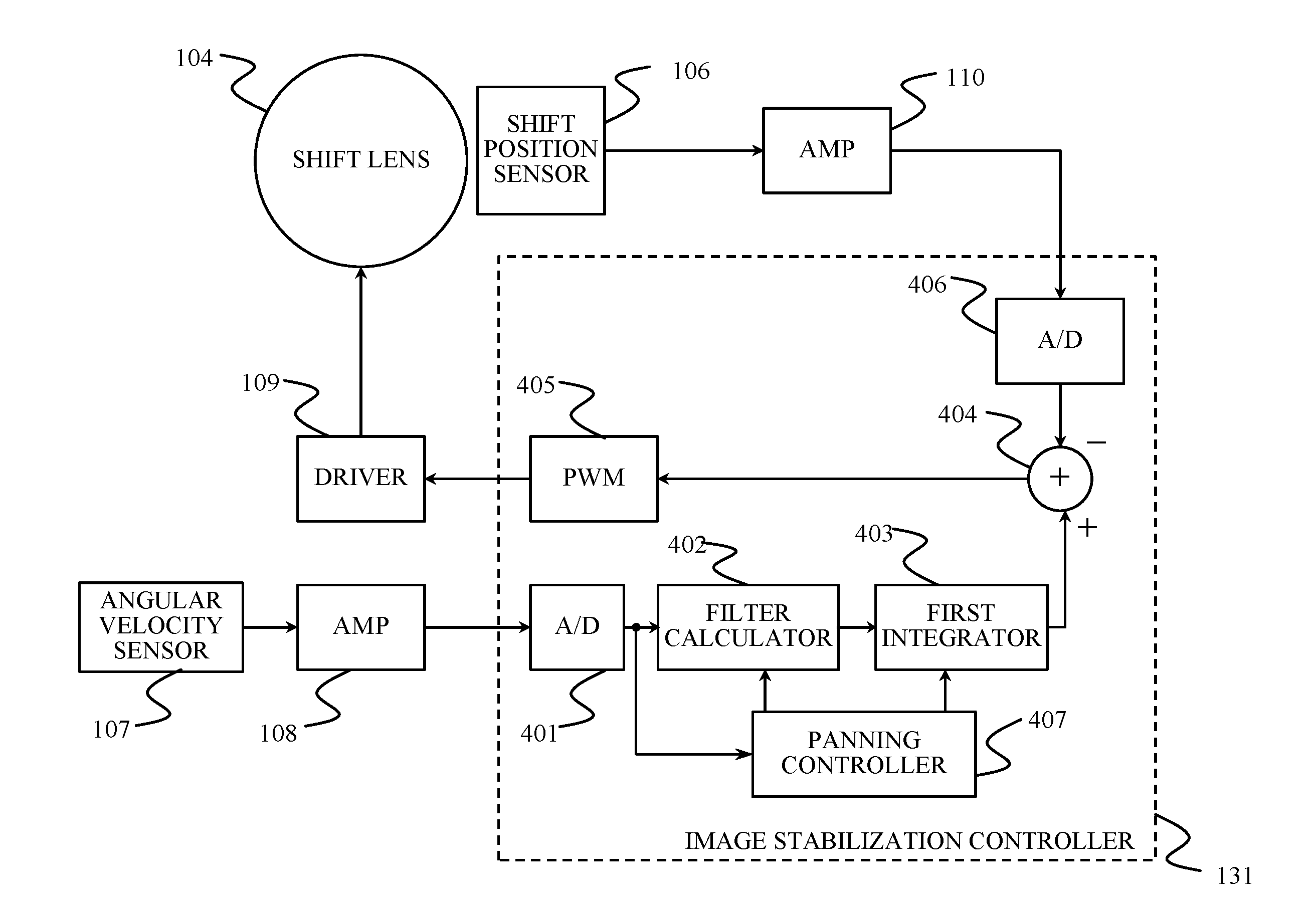
[0033]FIG. 3 shows a configuration of a lens-interchangeable camera (hereinafter simply referred to as “a camera”) 100 as an image capturing apparatus that is a first embodiment (Embodiment 1) of the present invention.

[0034]The camera 100 is provided with an image capturing lens unit 101 that is an image capturing optical system causing light from an object to form an optical image (object image). The image capturing lens unit 101 includes a main lens system 102, a zoom lens 103 that is movable in an optical axis direction in which an optical axis of the image capturing lens unit 101 extends to vary a focal length of the image capturing lens unit 101, and a focus lens (not shown) that is movable in the optical axis direction to perform focusing. The image capturing lens unit 101 further includes a shift lens 104 that is an optical element constituting part thereof.

[0035]The shift lens 104 is a shift element that is movable (or shiftable) in directions orthogonal to the optical axis ...

embodiment 2

[0117]Next, description will be made of a camera as an image capturing apparatus that is a second embodiment (Embodiment 2) of the present invention. A configuration of the camera of this embodiment is common to that of the camera 100 of Embodiment 1, and therefore components of the camera in this embodiment are denoted by the same reference numerals as those in Embodiment 1.

[0118]Embodiment 1 described the case where the object angular velocity calculator 134 sends the pre-exposure relative object angular velocity and the calculation time at which the calculation thereof was made to the follow shot controller 132 and where the follow shot controller 132 accumulates the sets of the pre-exposure relative object angular velocity and the calculation time as the pre-exposure angular velocity history. Embodiment 2 will describe a case where the object angular velocity calculator 134 sends to the follow shot controller 132, in addition to the pre-exposure relative object angular velocity ...

embodiment 3

[0131]Next, description will be made of a camera as an image capturing apparatus that is a third embodiment (Embodiment 3) of the present invention. A configuration of the camera of this embodiment is common to that of the camera 100 of Embodiment 1, and therefore components of the camera in this embodiment are denoted by the same reference numerals as those in Embodiment 1.

[0132]Embodiments 1 and 2 described the case where the in-exposure relative object angular velocity is calculated only once before the exposure and the follow shot assist is performed depending on its calculation result. In this case, although a short exposure time causes no problem, a long exposure time may make it impossible to perform a good follow shot because of a change of the relative object angular velocity during that long exposure time. Thus, this embodiment sequentially calculates (repetitively updates) the in-exposure relative object angular velocity during the exposure time and controls the shift dri...


PUM


Abstract

In the image capturing apparatus, the controller controls an optical element, when a motion of the image capturing apparatus follows a motion of the object, by using first motion information obtained from a first detector to detect the motion of the image capturing apparatus and second motion information obtained from a second detector to detect the motion of the object. The calculator calculates prediction information on the motion of the object during an exposure time, by using the second information detected at multiple times before the exposure time. The controller uses the prediction information to control the optical element during the exposure time.

Description

FIELD OF THE INVENTION[0001]The present invention relates to a technique of reducing image blur in a so-called “follow shot”.DESCRIPTION OF THE RELATED ART[0002]The follow shot, which enables expressing a sense of speed of a moving object, is a technique of photography to acquire a captured image in which the object is still and a background flows, by panning an image capturing apparatus (camera) so as to follow the motion of the object. In such follow shot, a faster or slower panning speed than a motion velocity of the object generates a captured image including a blurred object image.[0003]Japanese Patent Laid-Open No. 04-163535 discloses a camera that corrects such object image blur by moving part of an optical system or an image sensor during image capturing (exposure) on a basis of an angular velocity of the object relative to the camera calculated before the image capturing and an angular velocity of the camera during the image capturing obtained from an angular velocity senso...

Claims


Application Information

Patent Timeline
IPC IPC(8): H04N5/235H04N5/232
CPCH04N5/2353H04N5/23254H04N5/23287H04N5/23258H04N23/6811H04N23/6812H04N23/687H04N23/73G02B27/64G02B27/646G03B15/16G03B2207/005H04N23/682
Inventor MUKUNASHI, MASAYUKI
Owner CANON KK
Why Eureka
Try Eureka