Printing Device and Control Method of a Printing Device

a printing device and control method technology, applied in the direction of visual presentation using printers, liquid/fluent solid measurement, instruments, etc., can solve the problem of insufficient power supply for printing operation

Active Publication Date: 2016-09-15
SEIKO EPSON CORP
View PDF6 Cites 8 Cited by
  • Summary
  • Abstract
  • Description
  • Claims
  • Application Information

AI Technical Summary

Benefits of technology

[0007]A printing device and a control method of a printing device according to one aspect of the invent

Problems solved by technology

Depending on the amount of power supplied to the external device, however, the printing dev

Method used


Image

  • Printing Device and Control Method of a Printing Device
  • Printing Device and Control Method of a Printing Device
  • Printing Device and Control Method of a Printing Device

Examples


embodiment 1

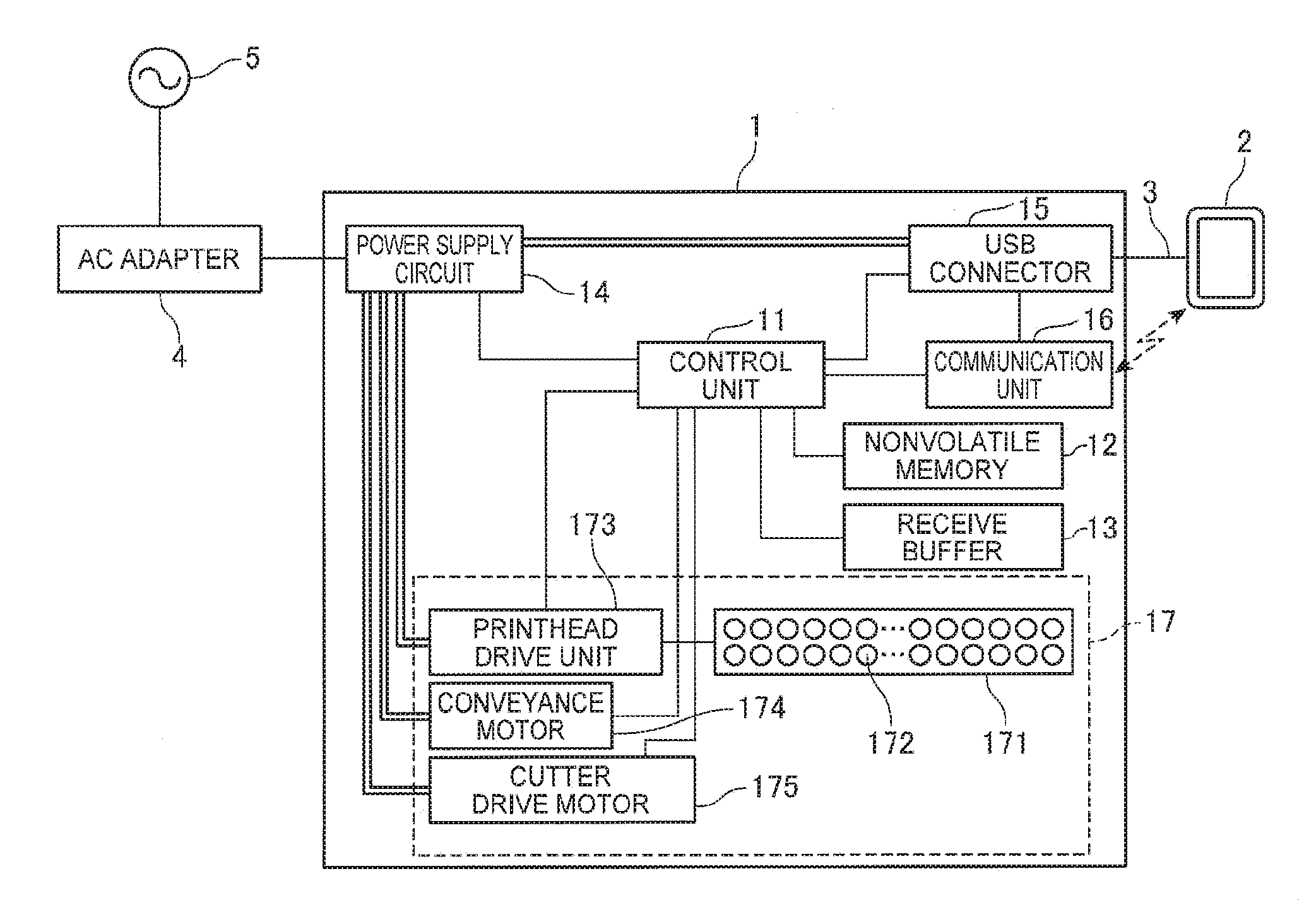
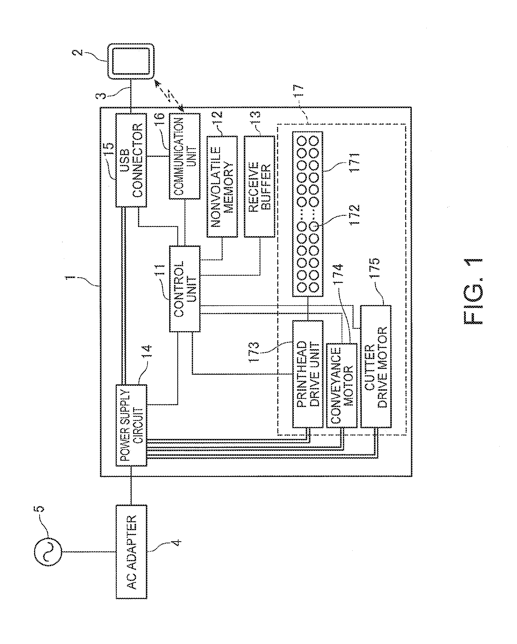
[0040]FIG. 1 is a function block diagram of a thermal printer 1 (printing device) according to the first embodiment of the invention.

[0041]The thermal printer 1 is a device that prints text and images on a recording medium based on data input from a smart device 2 (external device), and operates using power supplied from an AC adapter 4 connected to a commercial power source 5. The thermal printer 1 stores thermal roll paper as the recording medium in the printer, and prints text or images by applying heat to the recording surface of the thermal roll paper with a thermal head having heat elements as described below.

[0042]The smart device 2 is a terminal that can be easily carried around by the user, such as a smartphone or a tablet terminal. The smart device 2 has a communicator that sends and receives data using a specific communication protocol, and communicates with the thermal printer 1 through the communicator. The smart device 2 also has a storage battery (battery) and operate...

embodiment 2

[0095]A second embodiment of the invention is described next. The configuration of the thermal printer 1 in this embodiment is the same as in the first embodiment, and further description thereof is omitted.

[0096]The first embodiment describes supplying power to the smart device 2 according to the USB standard without communicating data through the USB connector 15. This second embodiment of the invention describes supplying power while using the USB standard for data communication with the smart device 2.

[0097]A first threshold voltage Vth1 indicating the voltage at which the smart device 2 stops charging, and a second threshold voltage Vth2 indicating the voltage at which the communication operation stops, are previously stored in the nonvolatile memory 12 of the thermal printer 1 in the second embodiment of the invention.

[0098]The first threshold voltage Vth1 and second threshold voltage Vth2 are set lower than 5 V. The first threshold voltage Vth1 is set higher than the second t...


PUM


Abstract

A printing device that and a control method of the printing device enable supplying power to a connected external device without affecting operation of the printing device. A thermal printer 1 has a USB connector 15 that connects to a smart device 2; a power supply circuit 14; a print mechanism 17 that operates using power supplied from the power supply circuit 14; a communicator 16 that communicates with the smart device 2; and a controller 11 that receives a command to start or stop operation of the print mechanism 17 from the smart device 2 through the communicator 16, and controls the power supply to the smart device 2 from the power supply circuit 14 according to the timing when operation of the print mechanism 17 starts and stops.

Description

[0001]This application claims priority under 35 U.S.C. §119 to Japanese Patent Application No. 2015-50504, filed on Mar. 3, 2015, the entire disclosure of which is expressly incorporated by reference herein.BACKGROUND[0002]1. Technical Field[0003]The present invention relates to a printing device and a method of controlling a printing device.[0004]2. Related Art[0005]Devices that operate using power supplied from an AC adapter are known from the literature (JP-A-2014-109919). Printing devices that can charge a mobile terminal or other external device are also known from the literature (JP-A-2005-125634). JP-A-2014-109919 describes a device that monitors and controls the load of the AC adapter, and controls the power that is consumed. JP-A-2005-125634 describes a printing device that can charge a mobile terminal whether or not the main power circuit of the printing device is on or off.[0006]The printing device described in JP-A-2014-109919 prints by using power supplied from an AC ad...

Claims


Application Information

Patent Timeline
IPC IPC(8): G06K15/00G06F1/32G06K15/02G06F1/26
CPCG06K15/4055G06F1/26G06K15/028G06K15/404G06F1/3287G06F3/1221B41J3/44B41J29/00G06F1/266G06F1/3206G06F1/3253G06F1/3284G06F1/3296Y02D10/00H02J7/00
Inventor UNO, AKIHIROYOSHIE, SHINICHI
Owner SEIKO EPSON CORP
Why Eureka
Try Eureka