Multiple Segment Lobe Pump

a multi-segment, lobe technology, applied in the direction of machines/engines, rotary/oscillating piston pump components, liquid fuel engines, etc., can solve the problems of limited wide-spread use, non-pulsating pumps are currently not manufactured, and the magnitude of pulses did not eliminate the non-continuous pump flow characteristic, etc., to reduce the flow pulsation and eliminate the cyclic variation in the total flow

Active Publication Date: 2016-09-29
OCOR CORP
View PDF2 Cites 4 Cited by
  • Summary
  • Abstract
  • Description
  • Claims
  • Application Information

AI Technical Summary

Benefits of technology

[0012]The individual pumps are positioned with a predetermined angular offset with respect to the lobes in each succeeding segment. Since the flow of each segment is additive, the timing of the segments eliminates the cyclic variation in the total flow resulting in smooth, continuous discharge flow. In one embodiment a three straight-sided lobe pump configuration with five pump segments per shaft, reduces the flow pulsations at both the inlet and discharge to less than one-percent of the total flow.

Problems solved by technology

However, such pumps produce flow pulsations that are undesirable in many applications and as a result, have limited their wide spread use.
The curved nesting lobe design significantly reduced the magnitude of the pulses but did not eliminate the non-continuous pump flow characteristic.
A three helical lobe, non-pulsating pump is currently not manufactured because of the geometric limitations related to the PCIR.
Adding the wrap angle required to seal a volume of flow within the pumping cavity and provide continuous pulse free flow, requires a PCIR of 240° resulting in an unworkably small inlet and discharge opening.

Method used


Image

  • Multiple Segment Lobe Pump
  • Multiple Segment Lobe Pump
  • Multiple Segment Lobe Pump

Examples


Embodiment Construction

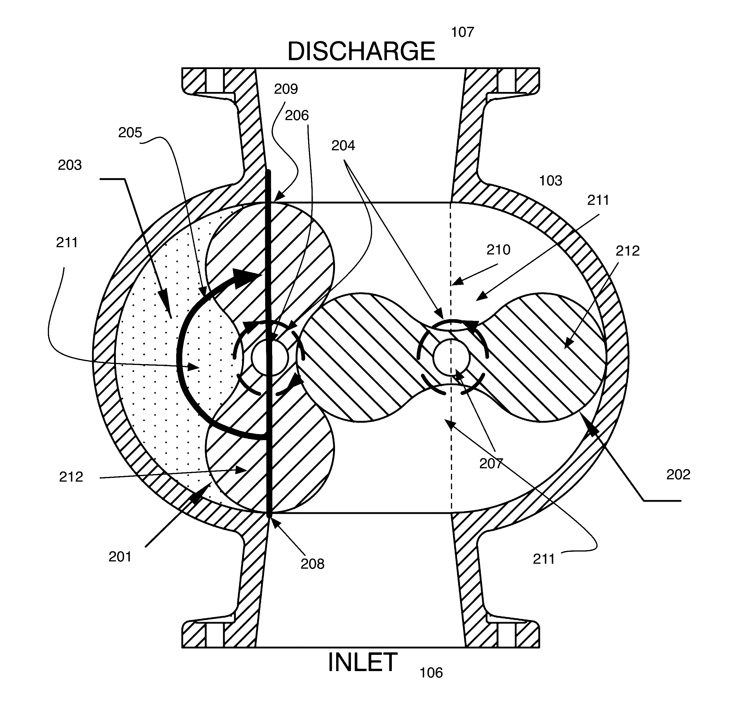
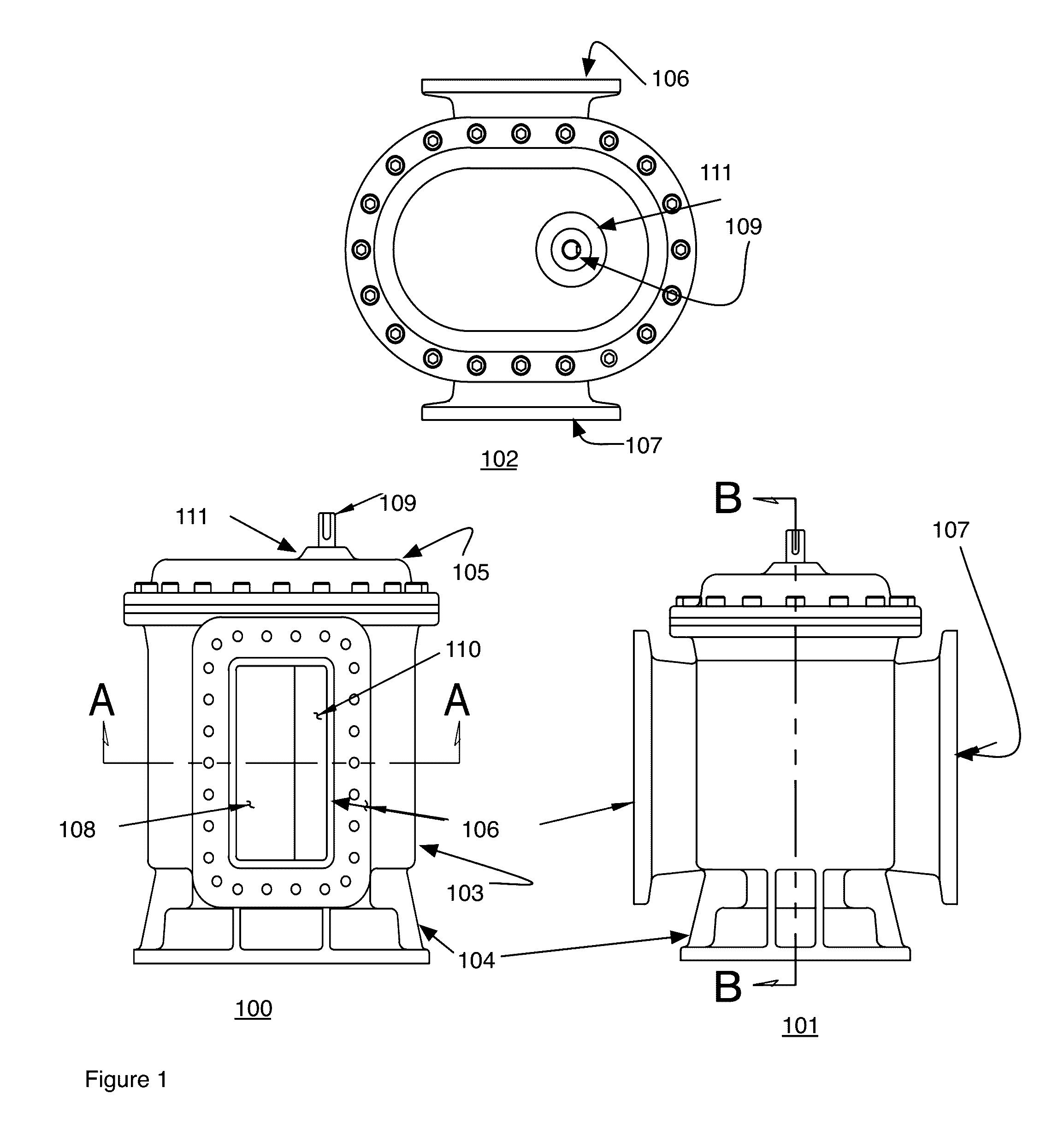
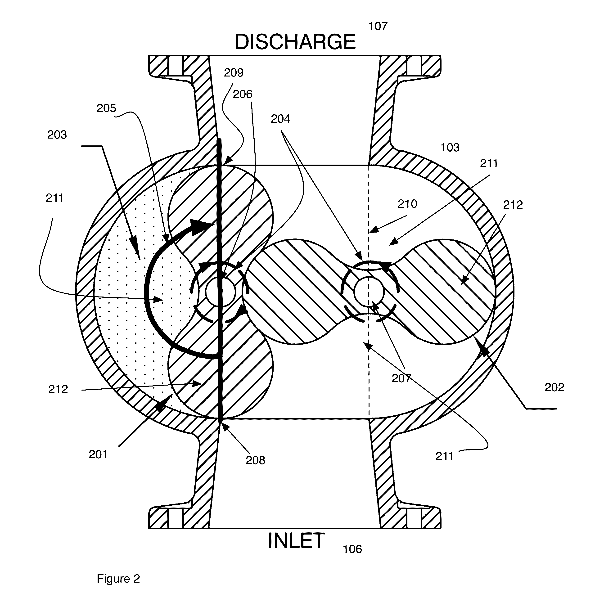
[0040]To fully explain how the basic prior art lobe pump operates, and to help explain the instant invention by contrast, FIGS. 1-6 are included that show several views of a prior art lobe pump. It should be understood and apparent however that some components and descriptions are common to both the prior art pumps and embodiments of the current invention. As an example both the prior art and the current invention include housings, inlets, outlets and at least a pair of rotors. Descriptions specific to embodiments of the instant invention, for brevity, avoid repeatedly restating these common features. The pump has two side-by-side rotors, each with two identical sets of lobes. FIG. 1 illustrates the three primary exterior views of the machine. FIGS. 2-5 illustrate interior sections and components. FIG. 6 shows a measure of performance.

[0041]Referring now to FIG. 1 a typical exterior housing for pumps of both prior art design and the current invention is shown. Three views are shown ...


PUM


Abstract

Designs for multiple segment lobe pumps are shown. The designs include pumps using rotors having two lobes to a plurality of lobes and segments that include two segments to a plurality of segments. Designs for both vertical, or straight walled conventional lobed rotors, as well as helical lobe rotors are shown. The designs are applicable to a variety of rotors and number of segments. In one particular case the designs enable a three lobe helical pump. Designs are also shown for separator plates used between the multiple segments. The separator float between the pairs of lobes in a segment and can also have a fixed position between the lobes by inclusion of end pieces that enable clamping of the separator plates in position.

Description

CROSS-REFERENCE TO RELATED APPLICATIONS[0001]This application claims the benefit of, and is a continuation in part, of U.S. Non-provisional patent application Ser. No. 13 / 917,560, filed Jun. 13, 2013, titled Multiple Segment Lobe Pump, currently pending and by the same inventor. Priority application Ser. No. 13 / 917,560 claims priority to U.S. Provisional Patent Application 61 / 667,556, filed Jul. 3, 2012, titled “Multiple Segment Lobe Pump”, by the same inventor.BACKGROUND OF THE INVENTION[0002]1. Technical Field[0003]The present invention relates to a multiple segment lobe pump with reduced or zero pulsations in the outflow.[0004]2. Related Background Art[0005]The first lobe (air) pump was invented in 1854 by a couple of wood mill owners in Connersville, Ind. named Francis and Philander Roots and became known as ‘The Roots Blower’. The design featured two side-by-side rotors that were each shaped sort of like a two dimensional hourglass. As the rotors turned, each delivered a ‘puff’...

Claims


Application Information

Patent Timeline
Patent Type & Authority Applications(United States)
IPC IPC(8): F04C2/12F04C15/06F04C15/00F04C13/00F04C14/02
CPCF04C2/126F04C13/001F04C14/02F04C15/008F04C2240/60F04C15/06F04C2240/20F04C2240/30F04C15/0073F01C17/02F01C21/108F04C2/123F04C11/001F04C15/0049
Inventor O'CONNOR, BRIAN J.
Owner OCOR CORP
Why Eureka
Try Eureka