Dual oil supply pump

a technology of oil supply pump and pump body, which is applied in the direction of piston pump, positive displacement liquid engine, liquid fuel engine, etc., can solve the problems of pump drawing a greater amount of oil and consuming the other pump, and the packaging efficiency of the pump is large, so as to reduce the flow pulsation, prevent flow imbalance and cavitation during operation, and maximize the packaging efficiency of the pump

Inactive Publication Date: 2005-08-18
GM GLOBAL TECH OPERATIONS LLC
View PDF6 Cites 40 Cited by
  • Summary
  • Abstract
  • Description
  • Claims
  • Application Information

AI Technical Summary

Benefits of technology

[0004] The present invention provides an oil pump assembly having first and second pump mechanisms contained within a common housing to maximize packaging efficiency of the pump. The pump assembly also provides adequate inlet oil flow to each of the pump mechanisms to prevent flow imbalance and cavitation during operation. Furthermore, the pump mechanisms are offset in phase to reduce flow pulsations through the housing to reduce pump noise and vibration.

Problems solved by technology

While this pump meets engine oil flow requirements, its packaging requires a large amount of volume.
Dual oil supply pumps which are contained within a common housing to reduce packaging volume may under high flow rates experience flow imbalance between the pumps.
Specifically, when one pump draws a greater volume than its counterpart does, the pump drawing the greater amount of oil can starve the other pump.
Additionally, pumps contained within a common housing usually operate on the same frequency resulting in flow pulsations that are translated to pressure fluctuations though the pump, which may cause undesirable pump vibration and noise.

Method used


Image

  • Dual oil supply pump
  • Dual oil supply pump
  • Dual oil supply pump

Examples


Embodiment Construction

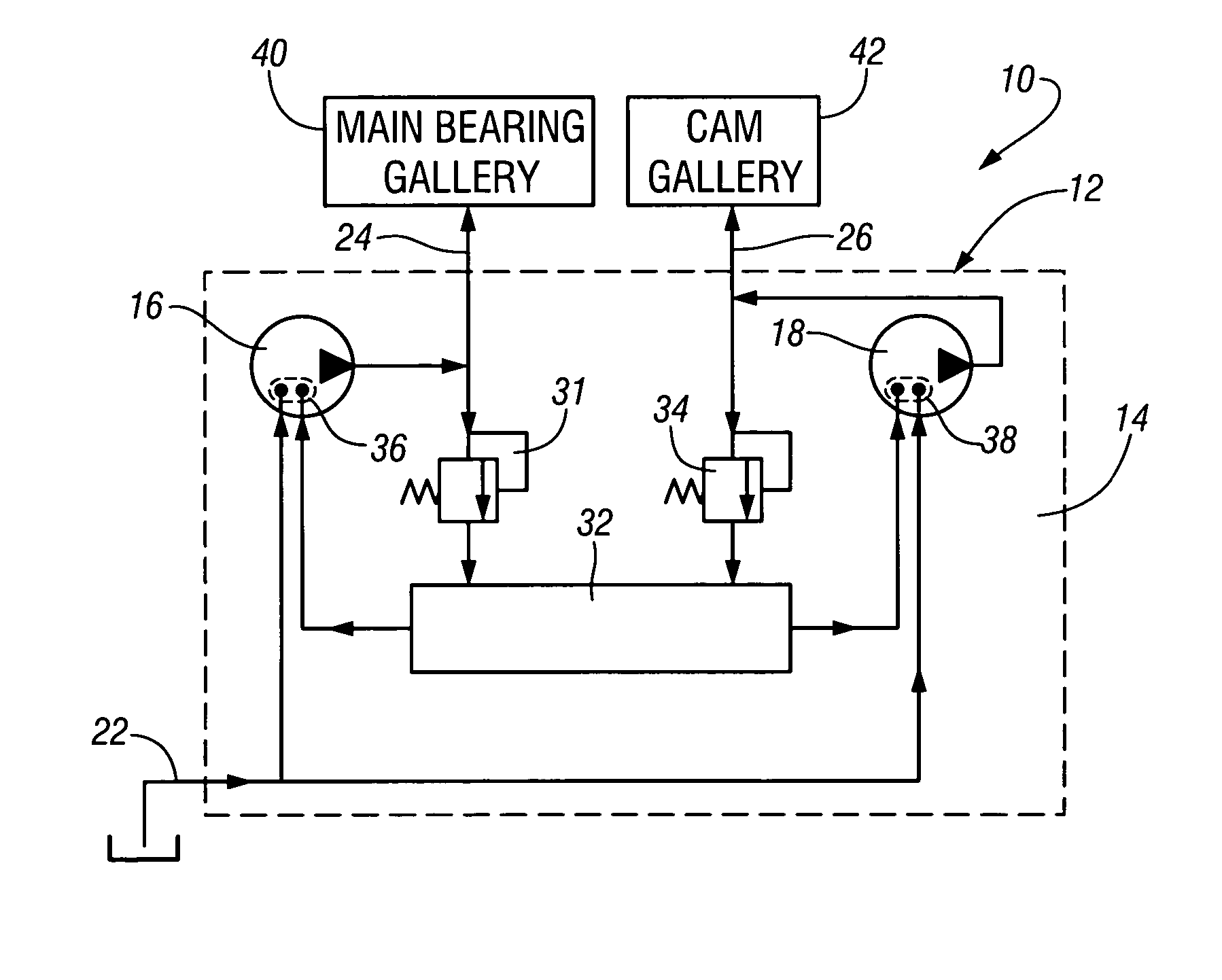
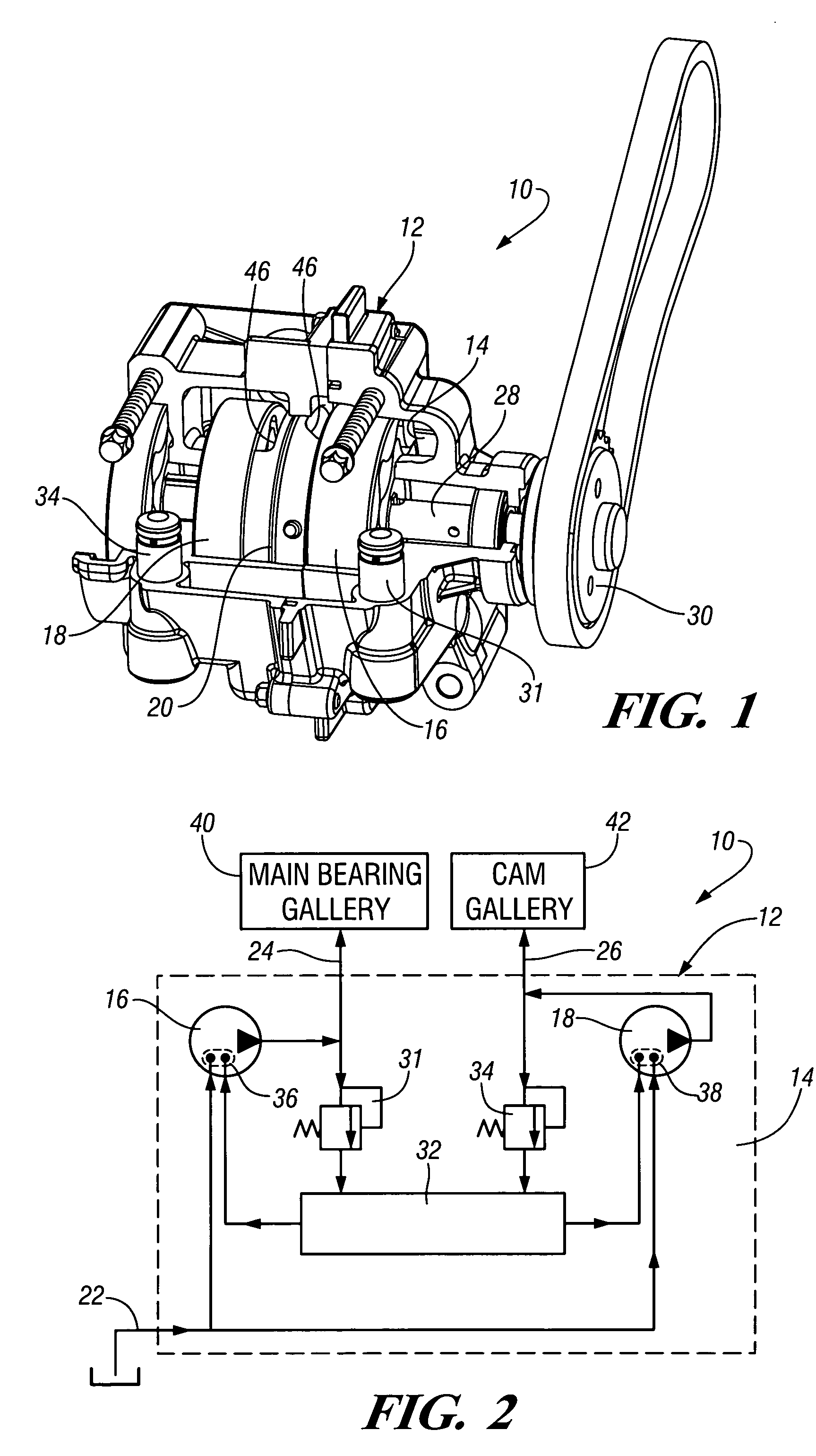
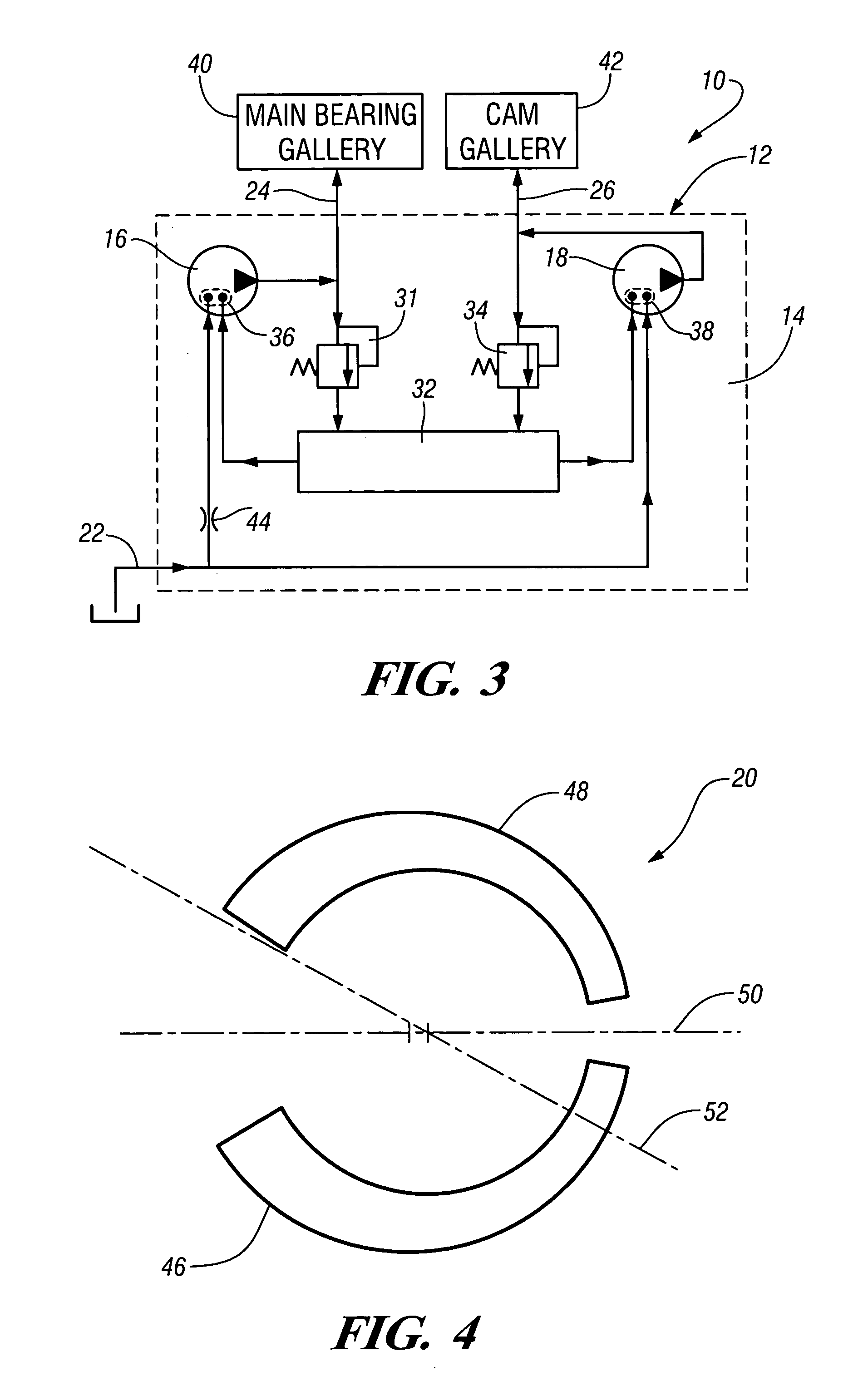
[0011] Referring now to FIGS. 1 and 2 of the drawings in detail, numeral 10 generally indicates an engine oil pump assembly. The pump assembly 10 includes a housing 12 defining an interior cavity 14 containing first and second pump mechanisms 16, 18 and a central port plate 20. The housing includes a common inlet 22 for feeding both pump mechanisms 16, 18, and first and second outlets 24, 26 connected with the separate pump mechanisms 16, 18. A shaft 28 having an external drive member 30 extends longitudinally through the housing 12 and drives both pump mechanisms 16, 18 at the same rotational velocity. Preferably, the pump mechanisms 16, 18 are positive displacement pumps such as gerotors. If desired, the first pump mechanism 16 may be advanced on the shaft 28 relative to the second pump 18 so that the pumps operate out of phase to reduce pulsation and vibration of the oil pump assembly 10. In addition, the pump mechanisms 16, 18 may have different displacements or flow rates if de...


PUM


Abstract

An automotive engine oil pump assembly having first and second pump mechanisms contained within a common housing. A shaft rotatably supported in the housing drives the pump mechanisms in a conventional manner. The pump mechanisms are offset in phase to reduce flow pulsations through the housing and limit pump noise and vibration. The first pump mechanism communicates with a common inlet and first outlet of the housing. The second pump mechanism communicates with the common inlet and second outlet of the housing. A common reservoir connected to inlets of the first and second oil pump mechanisms provides a supplemental oil source to balance oil pressures at the pump inlets to prevent pump cavitation and further reduce pump noise and vibration.

Description

TECHNICAL FIELD [0001] This invention relates to engine oil pumps and, more particularly, to dual oil supply pumps for use in automotive lubrication applications. BACKGROUND OF THE INVENTION [0002] Dual oil supply pumps are used primarily in conjunction with industrial hydraulic applications. However, dual oil supply pumps have also been used in automotive applications. One such automotive dual oil supply pump utilizes two individual oil pumps each having a discrete housing. While this pump meets engine oil flow requirements, its packaging requires a large amount of volume. [0003] Dual oil supply pumps which are contained within a common housing to reduce packaging volume may under high flow rates experience flow imbalance between the pumps. Specifically, when one pump draws a greater volume than its counterpart does, the pump drawing the greater amount of oil can starve the other pump. Additionally, pumps contained within a common housing usually operate on the same frequency resul...

Claims


Application Information

Patent Timeline
Patent Type & Authority Applications(United States)
IPC IPC(8): F04B23/00F04B23/06F04B23/08F04C2/10F04C11/00F04C14/02F04C14/26F16N13/00
CPCF04B23/06F04C2/102F04C14/26F04C14/02F04C11/001
Inventor STANLEY, DAVID R.WHITE, BRIAN D.
Owner GM GLOBAL TECH OPERATIONS LLC
Why Eureka
Try Eureka