
Fuel cell stack assembly

a fuel cell and stack technology, applied in the direction of fuel cells, solid electrolyte fuel cells, cell components, etc., can solve the problems of inability to maintain uniform tightening force, inability to meet the needs of customers, etc., to achieve high fastening force, wide elasticity range of wires, and constant surface pressure

Inactive Publication Date: 2009-09-10
HYUNDAI MOTOR CO LTD +1
View PDF4 Cites 7 Cited by
  • Summary
  • Abstract
  • Description
  • Claims
  • Application Information

AI Technical Summary

Benefits of technology

[0014]The present invention has been made in an effort to solve the above-described problems associated with prior art. The present invention is directed to a fuel cell stack assembly which can maintain a constant surface pressure on the fuel cell by utilizing a wide elasticity range of the wire, and ensure a high fastening force even with a small amount of material, thus making the fuel cell lightweight and maximizing the package efficiency.
[0016]Preferably, the tensioner may be mounted on the top surface of the upper end plate by means of a tension bolt such that the height of the tensioner can be adjusted by the tension bolt, thereby the tension of the wire being able to be adjusted.

Problems solved by technology

The prior art fuel cell stack, however, has drawbacks.
For instance, since the gasket is often made from a rubber material having visco-elastic property that varies depending on ambient temperature of the stack, initial tightening force may be weakened as time goes by and may eventually fail to maintain the tightening force uniformly.
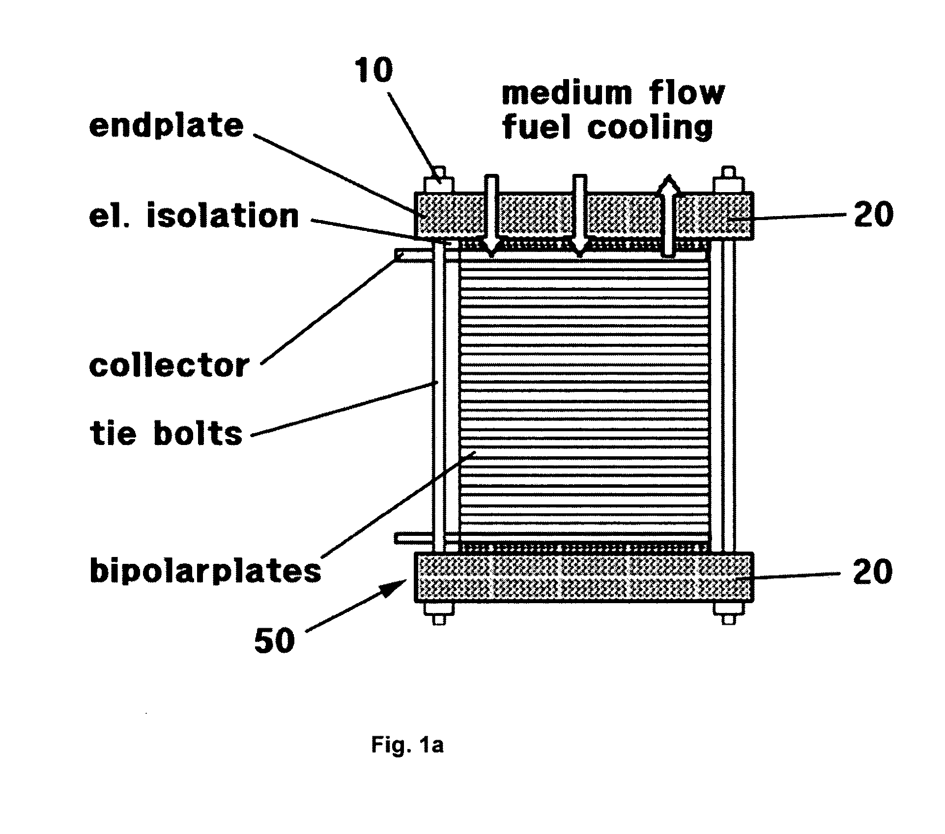
The fuel cell stack as shown in FIG. 1A has drawbacks in that since the overall volume of a stack 50 is increased, it is difficult to package the stack 50.
Moreover, the weight of the stack 50 is increased due to the weight of the bolts 10, and stress is concentrated on a thread portion of the bolt 10 when a load acts in the longitudinal direction of the bolt 10, and thus the thread portion may be easily damaged.
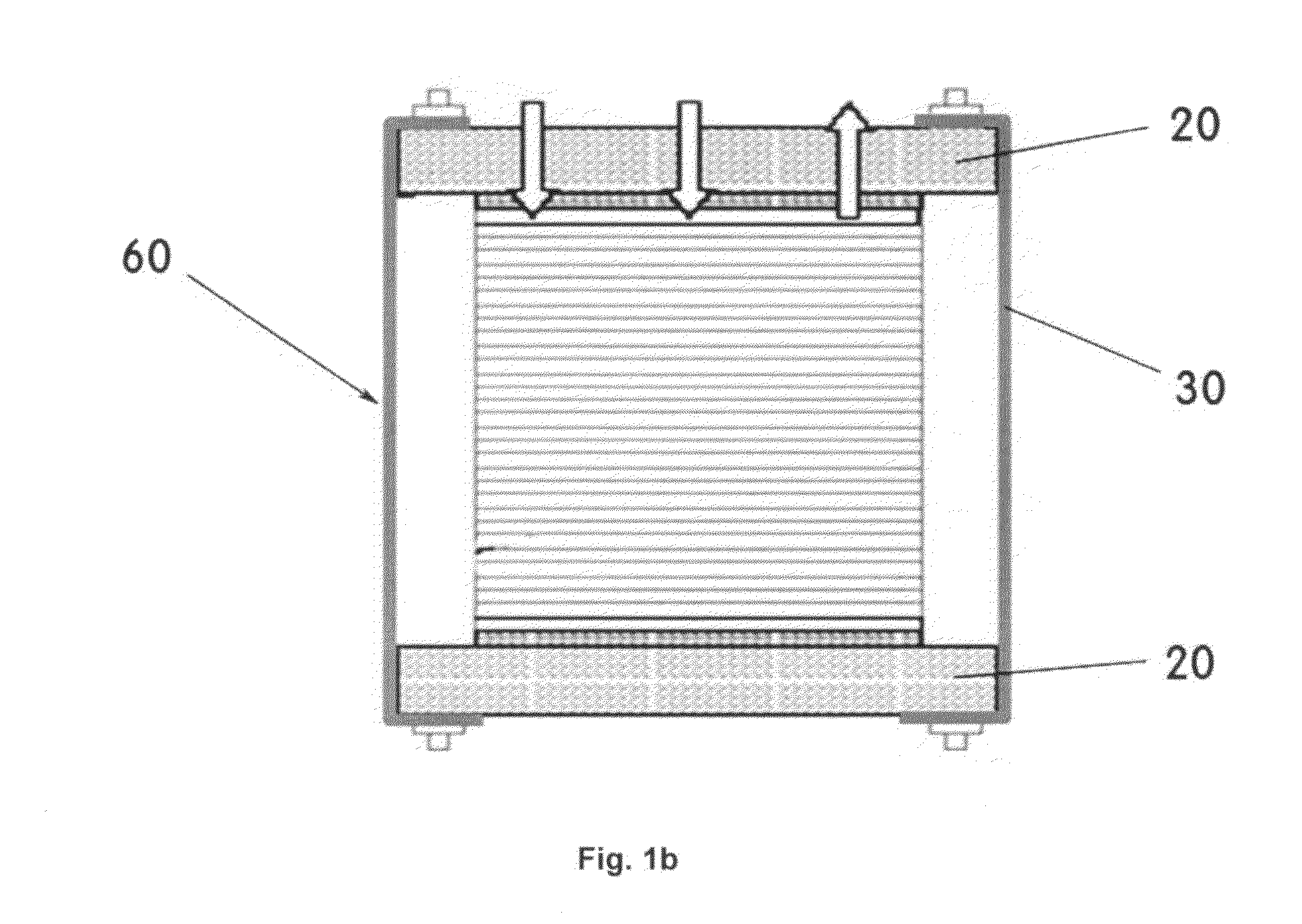
The fuel cell stack as shown in FIG. 1B has drawbacks in that it is difficult to control the surface pressure with respect to a stack 60, and it is also difficult to control the initial surface pressure since the size of the bands 30 is not uniform.

Method used


Image

  • Fuel cell stack assembly
  • Fuel cell stack assembly
  • Fuel cell stack assembly

Examples


Embodiment Construction

[0030]Reference will now be made in detail to the preferred embodiments of the present invention, examples of which are illustrated in the drawings attached hereinafter, wherein like reference numerals refer to like elements throughout. The embodiments are described below so as to explain the present invention by referring to the figures.

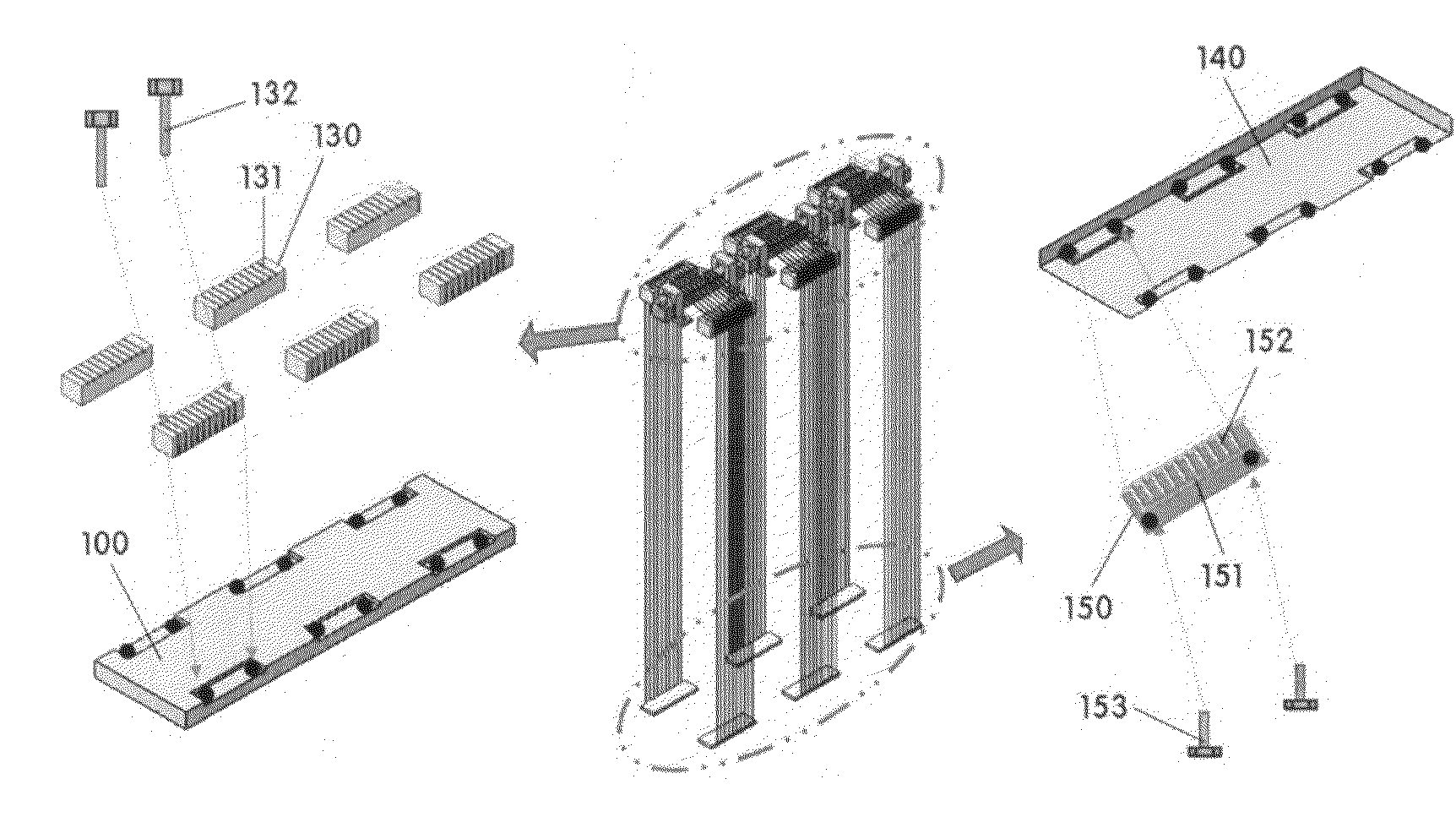
[0031]FIG. 2 is a schematic top view of a fuel cell stack assembly in accordance with a preferred embodiment of the present invention, FIG. 3 is a schematic bottom view thereof, and FIGS. 4 to 6 are detailed views thereof.

[0032]In a preferred embodiment of the present invention, as shown in FIGS. 2 and 3, a fuel cell stack is assembled by winding a plurality of wire 200 on a tensioner 110 and an upper guide 130, which are mounted on a portion of the top surface of an upper end plate 100, and inserting a locking member 160 into a lower guide 150 mounted on a portion of the bottom surface of a lower end plate 140, thus maintaining a constant surface p...


PUM

PropertyMeasurementUnit
diameteraaaaaaaaaa
tensile strengthaaaaaaaaaa
diameteraaaaaaaaaa

Abstract

A fuel cell stack assembly includes a wire for assembling a fuel cell stack, which can maintain a constant surface pressure on the fuel cell by utilizing a wide elasticity range of the wire and ensure a high fastening force even with a small amount of material, thus making the fuel cell lightweight and maximizing the package efficiency. For this purpose, the present invention provides a fuel cell stack assembly including: at least one wire for fastening end plates mounted on both end portions of a fuel cell stack; at least one tensioner mounted on at least one portion of the top surface of an upper end plate; at least one tension guide each of which includes a central guide for guiding up and down movement of the tensioner and surrounds the tensioner; at least one upper guide mounted on both sides of the top surface of the upper end plate for guiding the wire; and at least one lower guide mounted on both sides of the bottom surface of a lower end plate for guiding the wire.

Description

CROSS-REFERENCE TO RELATED APPLICATION[0001]This application claims under 35 U.S.C. §119(a) the benefit of Korean Patent Application No. 10-2007-0129544 filed Dec. 13, 2007, the entire contents of which are incorporated herein by reference.BACKGROUND[0002](a) Technical Field[0003]The present invention relates to a fuel cell stack assembly, in which a wire is used to assemble a fuel cell stack while maintaining a constant surface pressure on each fuel cell by utilizing a wide elasticity range of the wire, which can ensure a high fastening force even with a small amount of material, thus making the fuel cell lightweight and maximizing the package efficiency.[0004](b) Background Art[0005]In general, a fuel cell stack refers to an electrical energy generating device, in which a plurality of unit cells are piled up.[0006]Such a fuel cell stack has a structure in which one to two hundred separators, gas diffusion layers (GDLs), gaskets, and the like are stacked in orderly manner, and end ...

Claims


Application Information

Patent Timeline
Patent Type & Authority Applications(United States)
IPC IPC(8): H01M2/02
CPCY02E60/50H01M8/248H01M8/24
Inventor SUH, JUNG DOLEE, DAI GIL
Owner HYUNDAI MOTOR CO LTD
Learn More