Battery module, battery module system, and battery pack including same
A battery module and battery cell technology, which is applied to battery pack components, batteries, secondary batteries, etc., can solve problems such as battery cell expansion and battery module casing deformation.
- Summary
- Abstract
- Description
- Claims
- Application Information
AI Technical Summary
Problems solved by technology
Method used
Image
Examples
no. 1 example
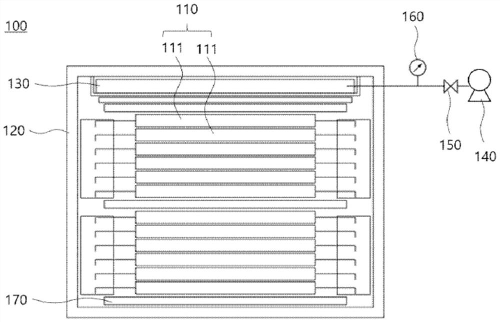
[0072] figure 2 is a schematic diagram of a battery module according to an embodiment of the present invention.
[0073] refer to figure 2 , the battery module 100 according to the present invention includes: a battery cell stack 110 formed by stacking n (n is an integer equal to or greater than 2) battery cells 111; a module case 120, so The module case 120 is configured to accommodate the battery cell stack 110; the duct 130 is configured to be stacked on one surface of the battery cell stack 110 and located between the battery cell stack 110 and the module case 120, and is configured to have a structure for the inflow of fluid; a fluid supply device 140, which is configured to be connected to the pipeline 130 and supply fluid to the pipeline 130; and a fluid control valve 150, which controls the The valve 150 is configured to be connected to the pipe and the fluid supply device 140 and to control the inflow of the fluid into the pipe 130 so as to keep the surface pressu...
no. 2 example
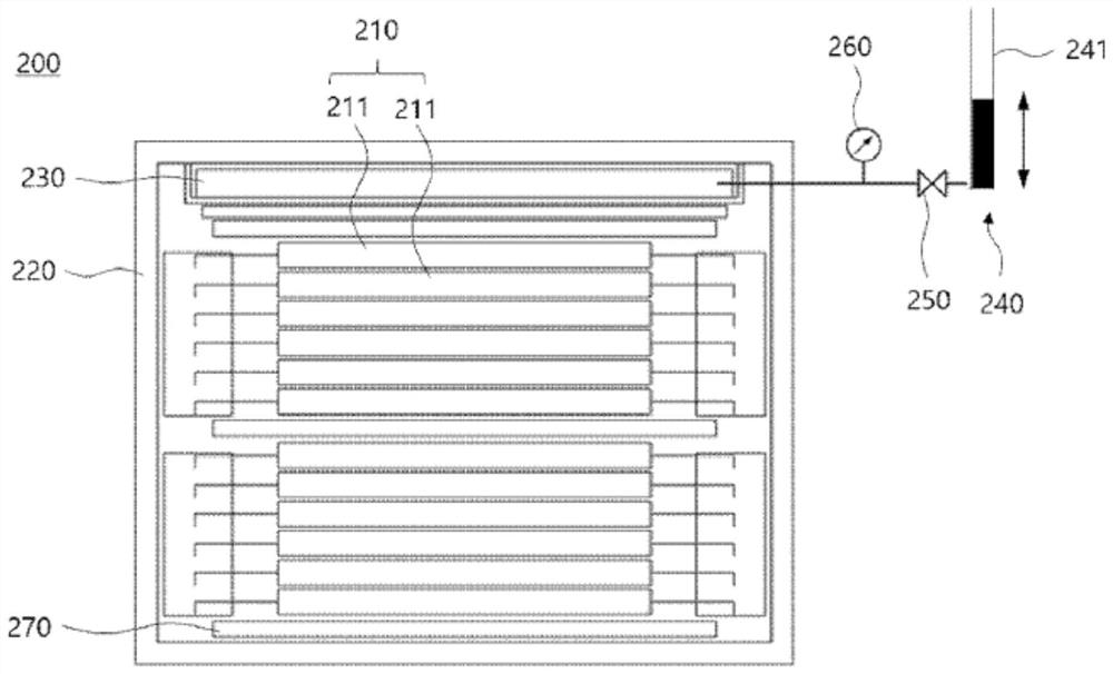
[0082] image 3 is a schematic diagram showing a battery module according to another embodiment of the present invention.
[0083] refer to image 3 , the battery module 200 according to the present invention includes: a battery cell stack 210 formed by stacking n (n is an integer equal to or greater than 2) battery cells 211; a module case 220, so The module case 220 is configured to accommodate the battery cell stack 210; the duct 230 is configured to be stacked on one surface of the battery cell stack 210 and located between the battery cell stack 210 and the module case 220, and is configured to have a structure for the inflow of fluid; a fluid supply device 240, which is configured to connect to the conduit 230 and supply fluid to the conduit 230; and a fluid control valve 250, which controls the The valve 250 is configured to be connected to the pipe and the fluid supply device 240, and to control the inflow of fluid into the pipe 230, thereby keeping the surface press...
no. 3 example
[0088] Figure 4 is a schematic diagram showing a battery module according to still another embodiment of the present invention.
[0089] refer to Figure 4 , the battery module 300 according to the present invention includes: a battery cell stack 310 produced by stacking n (n is an integer equal to or greater than 2) battery cells 311; a module case 320 , the module case 320 is configured to accommodate the battery cell stack 310; the duct 330 is configured to be stacked on one surface of the battery cell stack 310 and located between the battery cell stack 310 and the module between the housings 320 and configured to have a structure for fluid inflow; a fluid supply device 340 configured to be connected to and supply fluid to the pipe 330; and a fluid control valve 350, the The fluid control valve 350 is configured to be connected to the pipe and the fluid supply device 340 , and to control the inflow of fluid into the pipe 330 , thereby maintaining a constant surface pres...
PUM
 Abstract
Description
Claims
Application Information
 - R&D
- Intellectual Property
- Life Sciences
- Materials
- Tech Scout
- Unparalleled Data Quality
- Higher Quality Content
- 60% Fewer Hallucinations
Browse by: Latest US Patents, China's latest patents, Technical Efficacy Thesaurus, Application Domain, Technology Topic, Popular Technical Reports.
© 2025 PatSnap. All rights reserved.Legal|Privacy policy|Modern Slavery Act Transparency Statement|Sitemap|About US| Contact US: help@patsnap.com


