
Compressor and manufacture method thereof

A technology for compressors and metal gaskets, applied in the field of compressors, can solve problems such as classification difficulties, unusable asbestos materials, difficulties, etc., and achieve the effects of easy replacement and maintenance, increased surface pressure, and guaranteed sealing

Inactive Publication Date: 2009-06-10
SANYO ELECTRIC CO LTD
View PDF1 Cites 0 Cited by
  • Summary
  • Abstract
  • Description
  • Claims
  • Application Information

AI Technical Summary

Problems solved by technology

[0005] However, in recent years, because asbestos has adverse effects on the human body, asbestos materials cannot be used. As a gasket for such a compressor, it is necessary to use metals composed of cold-rolled steel sheets or stainless steel sheets, etc., as described in the above-mentioned patent documents. Gasket
[0006] However, since metal gaskets have very high thickness accuracy compared to asbestos gaskets, classification under the same nominal thickness conditions as described above becomes difficult
In addition, on this metal gasket, in order to improve its crimping strength and obtain the necessary sealing surface pressure, ribs are formed. However, when it is made into the same thickness dimension as the asbestos gasket, it cannot be reinforced. Processing or rib processing is extremely difficult

Method used


Image

  • Compressor and manufacture method thereof
  • Compressor and manufacture method thereof
  • Compressor and manufacture method thereof

Examples


Embodiment 1

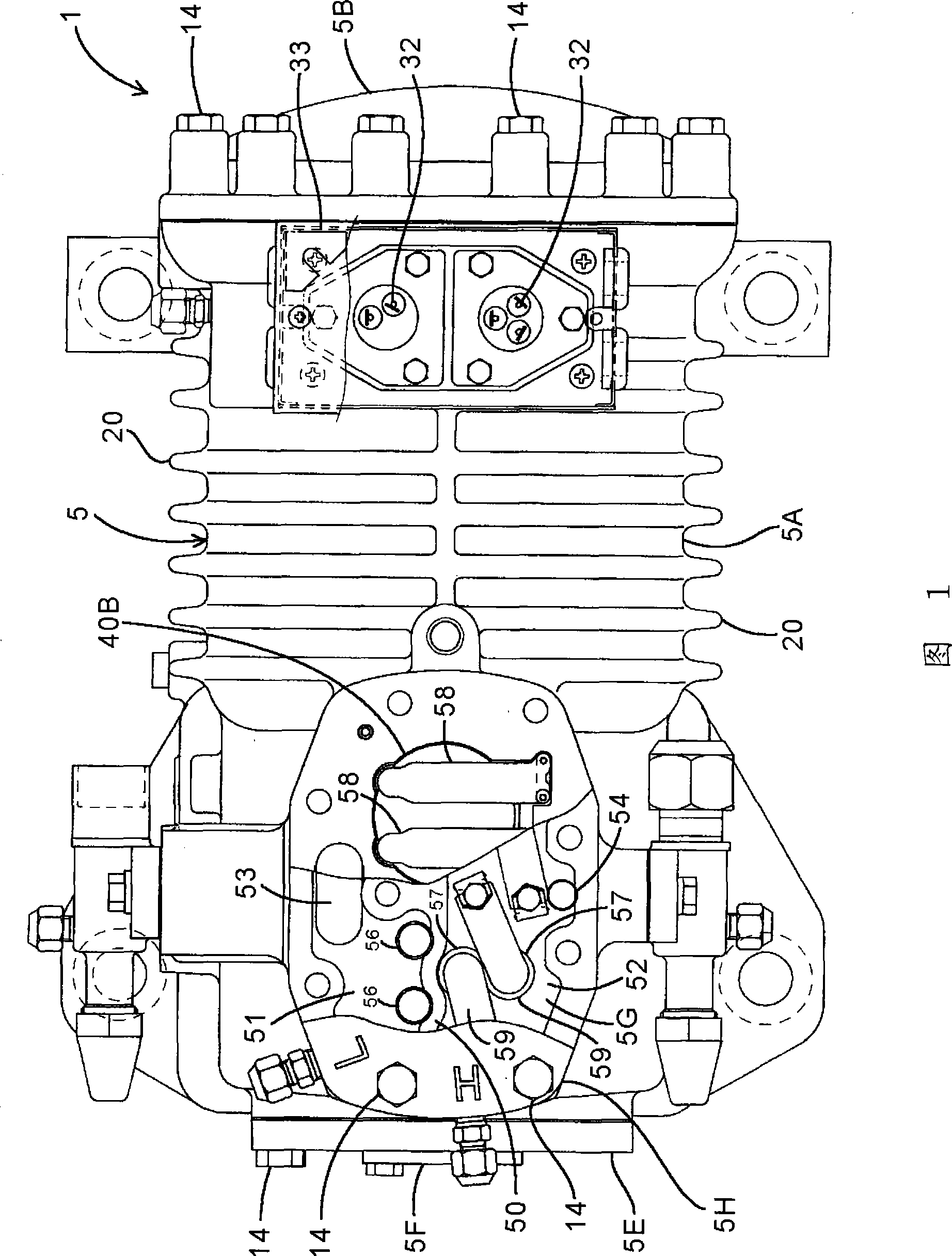
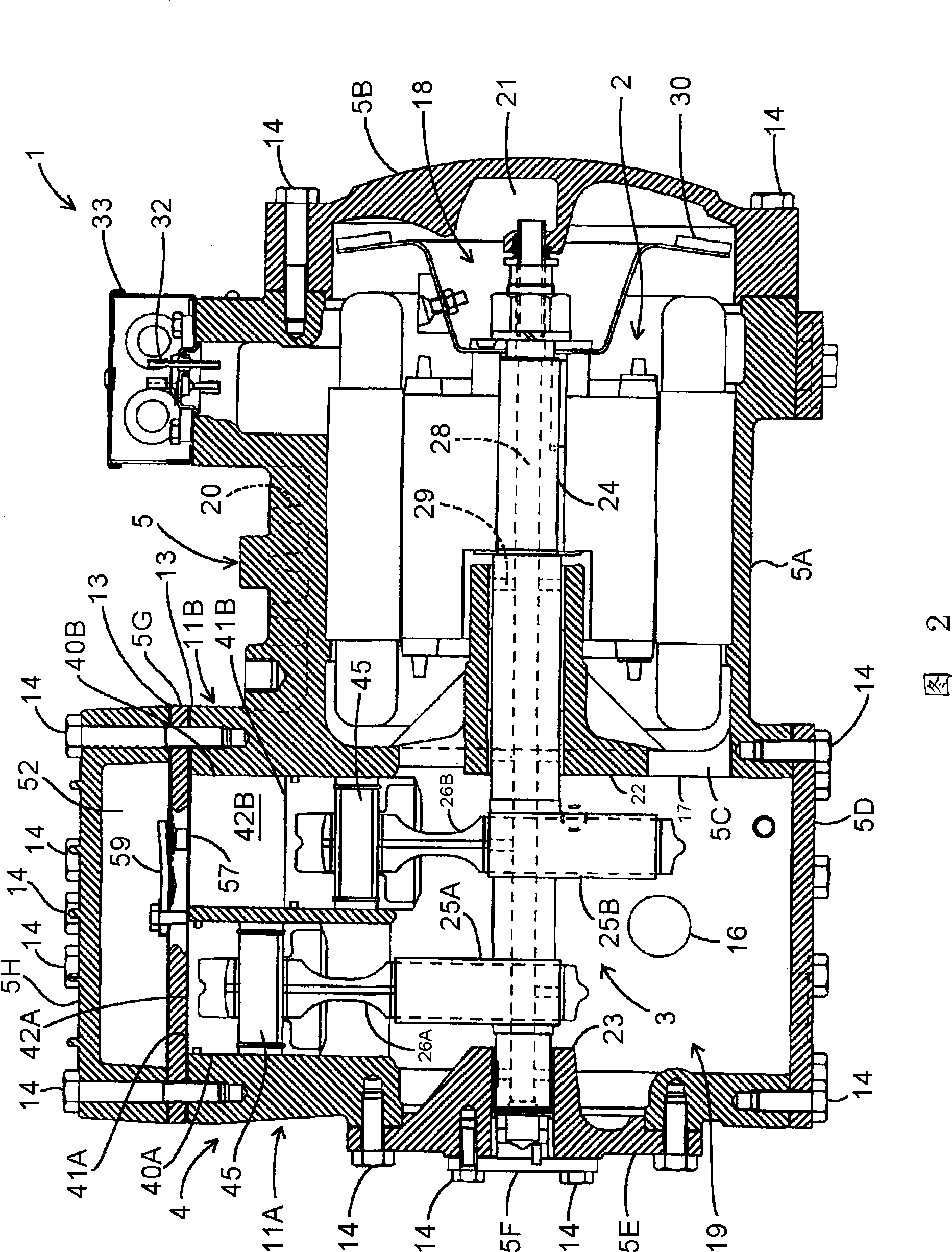
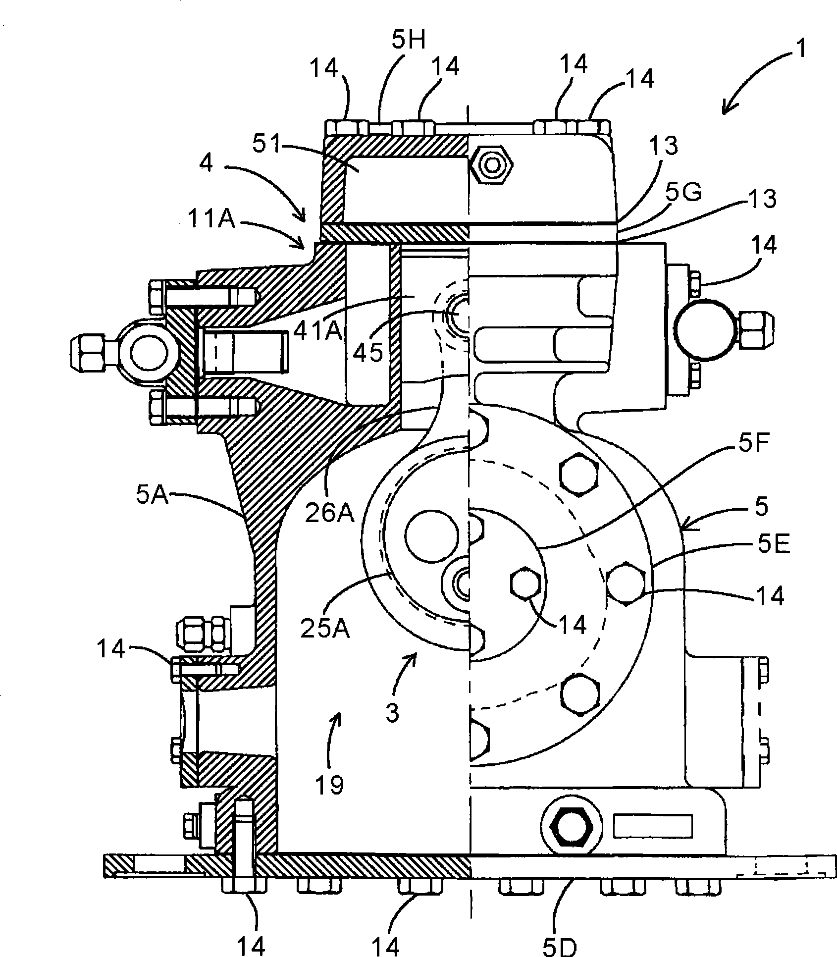
[0040] Fig. 1 is a top view of a semi-hermetic compressor 1 applicable to an embodiment of the present invention, and Fig. 2 is a longitudinal sectional front view of the compressor 1, image 3 is a partial longitudinal sectional side view of the compressor 1, and FIG. 4 is an exploded longitudinal sectional front view of the compressor 1, Figure 5 It is an exploded partial longitudinal sectional side view of the compressor 1, FIG. 6 is a top view of the first metal gasket 13A installed on the compressor 1, and FIG. 11 is a top view of the second metal gasket 13B installed on the compressor 1. .

[0041] The compressor 1 of the embodiment is composed of an electric motor (driving element) 2, a power conversion member 3, a compression member 4, and a housing 5 for accommodating them. The motor 2 generates rotational power, and the power conversion member 3 converts Rotational power is converted into reciprocating power, and the compression unit 4 is driven by the reciprocating...

Embodiment 2

[0075] In addition, FIG. 12 is an exploded partial longitudinal sectional side view showing an example of a V-type 4-cylinder reciprocating semi-hermetic compressor 1 . At this time, four air cylinders 40 are formed on the casing main body 5A, and pistons 41 are accommodated in each. Furthermore, between the housing body 5A and the valve plate 5G of each cylinder head 5H, a packing 13 in which the same metal gaskets 13A and 13B as described above are stacked is provided. Even in such a V-type compressor 1, the present invention is effective.

[0076] In addition, in the above-mentioned embodiments, two metal gaskets (the first metal gasket 13A and the second metal gasket 13B) are stacked and arranged between the valve plate 5G and the housing main body 5A, but it is not limited thereto. , It is also possible to adjust the top gap by overlapping three or more metal spacers (including all of the same plate thickness or any one or all of the plate thicknesses are different). In...


PUM


Abstract

The present invention provides a compressor that can easily adjust top clearance when metallic gasket is taken as a seal component between a valve plate and main body of a case. The structure of the compressor (1) is as following: a piston (41A) in advance and return movement do work inside an air cylinder (40A) of a main body of a case (5A) that composes a case (5); a cylinder cap (5H) is fixed on the main body of the case by threaded stud separating by a seal component (13) and a valve plate (5G); multiple metallic gaskets (13A, 13B) are superposed to compose the seal component between the valve plate and the main body of the case.

Description

technical field [0001] The invention relates to a compressor which uses bolts to fix a cylinder head on a shell body and performs compression and work by reciprocating motion of a piston and a manufacturing method thereof. Background technique [0002] Conventionally, in a reciprocating semi-hermetic compressor in which a piston reciprocates in a cylinder to perform work by compressing a refrigerant, a valve plate and a cylinder head are fixed to a casing main body with bolts to form a casing. In addition, seals are provided between the cylinder head and the valve plate, and between the valve plate and the housing main body to seal between the components (for example, refer to Patent Document 1). [0003] Patent Document 1: Japanese Patent Laid-Open No. 2004-301071 [0004] As a seal in this case, a gasket made of asbestos has conventionally been generally used. In addition, in such a reciprocating compressor, the top clearance of the piston (the clearance between the cyli...

Claims


Application Information

Patent Timeline
Patent Type & Authority Applications(China)
IPC IPC(8): F04B39/00F04B37/12F04B39/12
Inventor 坂本泰生杉本和禧小池良明板桥真也
Owner SANYO ELECTRIC CO LTD
Learn More