
Fuel cell

A technology for fuel cells and battery cells, applied in fuel cells, fuel cell additives, fuel cell grouping, etc., can solve problems such as performance degradation, uneven surface pressure, waste, etc., to achieve the effect of miniaturization

Inactive Publication Date: 2015-07-01
NISSAN MOTOR CO LTD
View PDF6 Cites 0 Cited by
  • Summary
  • Abstract
  • Description
  • Claims
  • Application Information

AI Technical Summary

Problems solved by technology

[0005] However, in the fuel cell system described in the aforementioned Patent Document 1, since the water reservoir portion in which the volume of the anode outlet internal manifold is enlarged is located on the lower side in the vertical direction than the gas flow path, the battery cell structure A part of it bulges out and tends to increase in size, and the assembly structure (Japanese: スタッキング structure) also becomes complicated
[0006] Moreover, since a part of the battery cell structure bulges, it tends to become a main cause of uneven surface pressure. As a result, the performance is lowered and the sealing performance is deteriorated, and the rectangular shape including the bulged part also becomes a wasteful area, which cannot be achieved. Avoid oversizing

Method used


Image

  • Fuel cell
  • Fuel cell
  • Fuel cell

Examples


Embodiment Construction

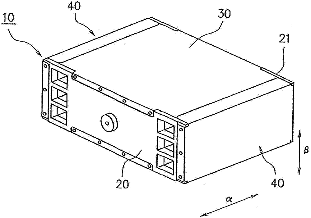
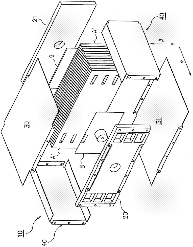
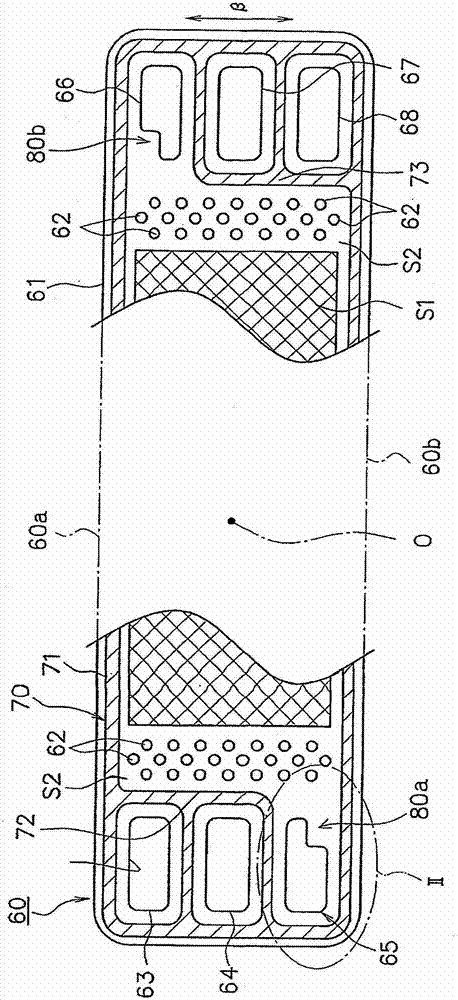
[0016] Hereinafter, embodiments of the present invention will be described with reference to the drawings. figure 1 It is a perspective view of a fuel cell stack formed by stacking fuel cells according to the first embodiment of the present invention, figure 2 is an exploded perspective view of the fuel cell stack. in addition, image 3 is a front view of a battery cell structure constituting a part of the fuel cell according to the first embodiment of the present invention, Figure 4 (A) is image 3 A partially enlarged view of the part indicated by the encircled line II in , Figure 4 (B) is an explanatory diagram showing the function of preventing the backflow of liquid water remaining in the anode outlet side manifold, Figure 5 It is a front view of an anode-side separator (cathode-side separator) constituting an example of a part of the fuel cell according to the first embodiment of the present invention.

[0017] Such as figure 1 , figure 2 As shown, the fuel c...


PUM


Abstract

To prevent inflow of liquid water into a power generating portion even if the liquid water remains in a manifold, and to enable size reduction by making constant the contact or surface pressure. According to the present invention, in a fuel cell comprising a power generating section including an electrolyte membrane joined between an anode and a cathode, and a manifold to cause inflow and outflow of an hydrogen containing gas and an oxygen containing gas separately from each other to the anode and cathode; the manifold is formed with an inflow preventing portion to prevent inflow of a liquid water remaining in the manifold, into the power generating portion.

Description

technical field [0001] The present invention relates to a fuel cell having a manifold for flowing out or flowing in a hydrogen-containing gas or an oxygen-containing gas. Background technique [0002] As such a fuel cell, Patent Document 1 discloses a structure named "fuel cell system". [0003] In the fuel cell system described in Patent Document 1, the internal manifold of the anode outlet is formed such that its volume expands in a region below the vertically lower side of the reaction region of the battery cell structure (Japanese: cell structure), Accompanying with this, the lower profile of the electrolyte membrane of each separator and battery cell structure is in the shape of partially protruding downward in the vertical direction, and the volume-enlarged part of the internal manifold of the anode outlet constitutes a channel for collecting the self-anode gas. A pool of condensed water discharged from the outlet of the flow path. [0004] Patent Document 1: Japanes...

Claims


Application Information

Patent Timeline
Patent Type & Authority Patents(China)
IPC IPC(8): H01M8/02H01M8/24H01M8/10
CPCY02E60/50H01M2008/1095H01M8/04156H01M8/04291H01M8/241H01M8/2483
Inventor 上原茂高西村英高影山和弘
Owner NISSAN MOTOR CO LTD
Learn More