
Shoe lace holder

a shoelace and lace technology, applied in the field of shoelace holders, can solve the problems of virtually impossible to re-tie the shoelace to not come undone, difficult to re-tie the shoelace, and troublesome people's shoelaces

Pending Publication Date: 2016-10-06
LACEJAM
View PDF0 Cites 2 Cited by
  • Summary
  • Abstract
  • Description
  • Claims
  • Application Information

AI Technical Summary

Benefits of technology

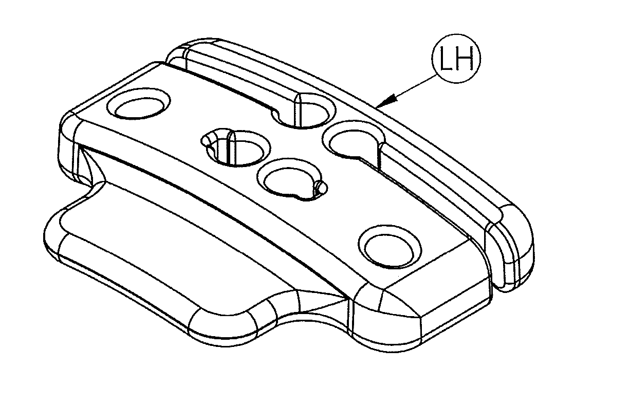
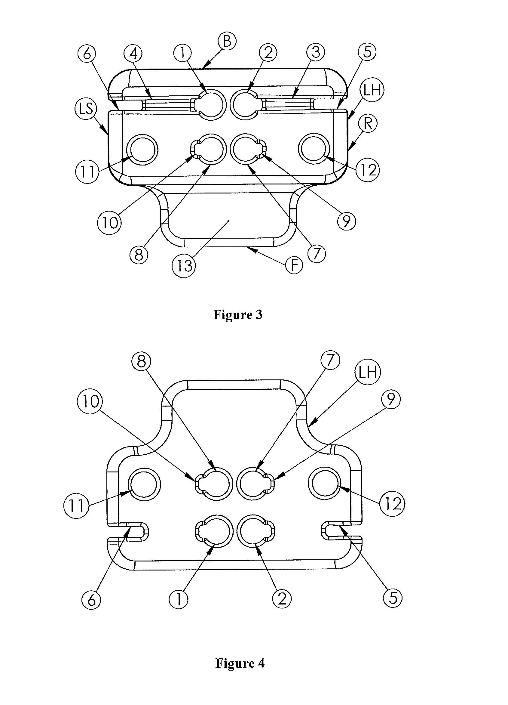
[0014]d) at least two further holes spaced apart from one another towards and adjacent a side edge of the body member, the two further holes adapted to accommodate and allow a shoe lace to pass there through,wherein, when attached to a shoe, the shoe lace holder in combination with the respective holes and slots engaging with the lace interweaved therein prevents a shoe lace from inadvertently untying during use of the shoe by a user.

Problems solved by technology

The tying of shoe laces can be problematic to some people, especially kids or those medically or mentally impaired.
Also it can be difficult to re tie a shoe lace during an outdoor game where the shoe and shoe laces are covered in mud or if the persons fingers are numb from the cold.
Sometimes the laces get wet, causing them to come undone, and once wet, it can be virtually impossible to re-tie the lace to not come undone again.
A shoe lace tied traditionally, whether for everyday use and / or sports, can and does come undone accidentally and unintentionally.
Even the use of a double bow does not eliminate the possibility of the shoe lace accidentally becoming undone.
The shape and cumbersome nature of the alternatives also introduce some factors which counter the usefulness and effective final use of the apparatus, in that in some instances, not just limited to sports, the shoe lace could still accidentally come undone.
Moving parts can break and wear out and some shapes are not suitable for contact sports where injury could be caused by the use of such an apparatus, rendering the use of the apparatus illegal or useless to that particular sport and / or use.

Method used


Image

  • Shoe lace holder
  • Shoe lace holder
  • Shoe lace holder

Examples


Embodiment Construction

)

[0051]The following description will describe the invention in relation to preferred embodiments of the invention, namely a shoe lace holder. The invention is in no way limited to these preferred embodiments as they are purely to exemplify the invention only and that possible variations and modifications would be readily apparent without departing from the scope of the invention.

[0052]The shoe lace holder of the invention uses motion and forces in a unique way. The laces are fed through the shoe lace holder to literally “jam” the lace in place and prevent the lace from accidentally coming undone during sports and everyday use. With no moving parts, the shoe lace holder severely limits time wastage in tying and re-tying shoe laces. The shoe lace holder saves parents, referees, sports people and people in everyday life from annoying delays in re-tying shoe laces.

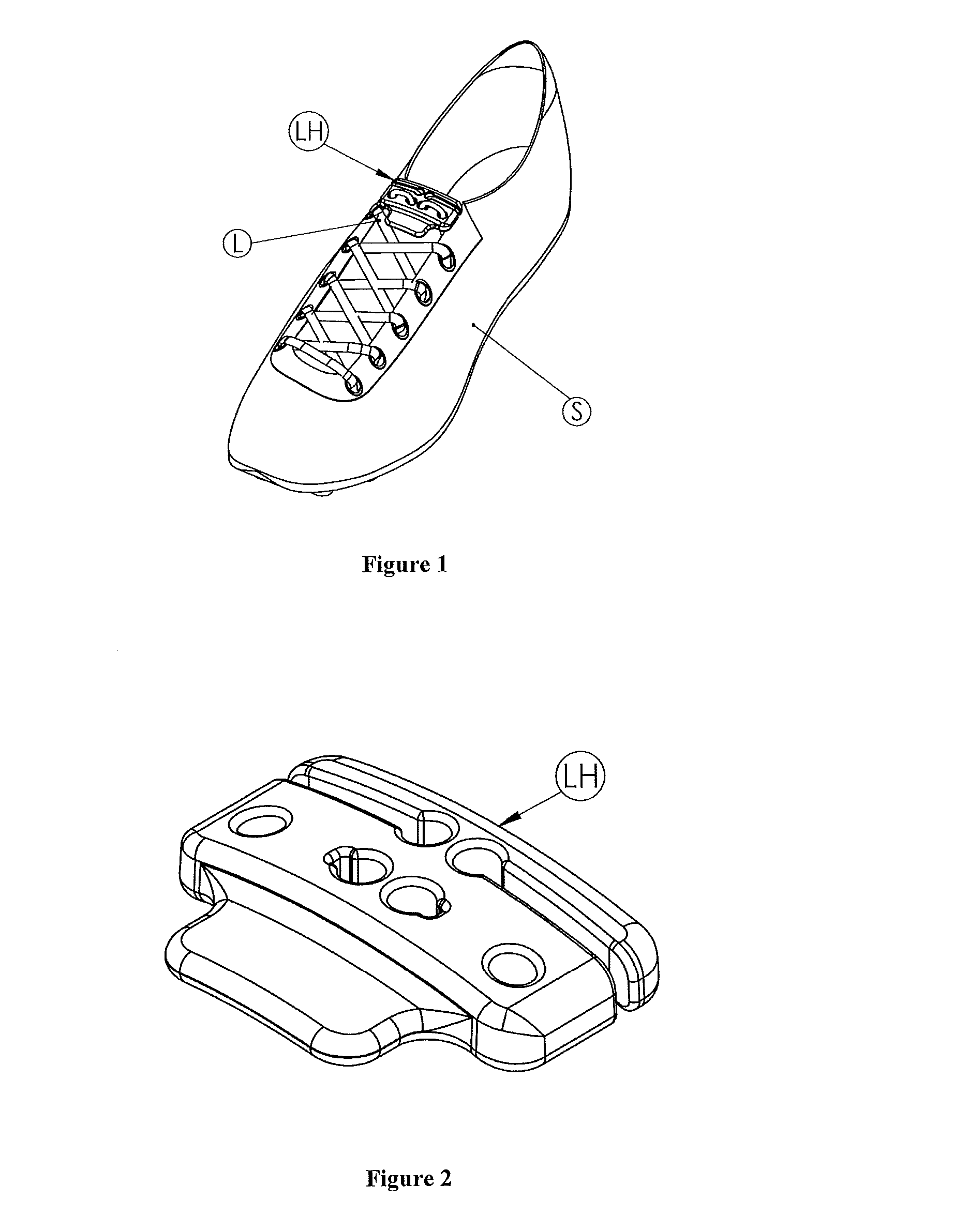
[0053]The shoe lace holder of the invention will now be described with reference to FIGS. 1 to 9.

[0054]FIG. 1 shoes a shoe ...


PUM


Abstract

A shoe lace holder (LH) to assist in the tying of shoe laces (L) and to prevent shoe laces inadvertently coming undone during use is disclosed. The shoelace holder includes a unitary body having top and bottom surfaces defined by a front edge, a back edge and side edges. The body includes at least one first hole (7) and at least one second hole (8), two slots (3, 4), which extend in opposite directions relative to each other, and at least two further holes (11, 12) spaced apart from each other. The holes allow a shoe lace to pass through, and the slots are adapted to engage a portion of the shoe lace there in. When attached to a shoe a shoe's laces are interwoven through the respective holes and slots to prevent the lace inadvertently untying in use. A method of securing a shoe lace to the shoe lace holder is also disclosed.

Description

FIELD OF THE INVENTION[0001]The invention relates to a Shoe Lace Holder to assist in the tying of shoe laces and to prevent shoe laces inadvertently coining undone during use.BACKGROUND OF INVENTION[0002]The tying of shoe laces can be problematic to some people, especially kids or those medically or mentally impaired. As well shoe laces can come undone, even if tied correctly, during everyday activities such as walking and playing sports. It not uncommon during sports games for shoe laces to come undone leading to the player effected having to re-tie the shoe lace meaning that the player affected is out of the game or the game is stopped while the effected person is re-tying the shoe lace. Also it can be difficult to re tie a shoe lace during an outdoor game where the shoe and shoe laces are covered in mud or if the persons fingers are numb from the cold. Sometimes the laces get wet, causing them to come undone, and once wet, it can be virtually impossible to re-tie the lace to not ...

Claims


Application Information

Patent Timeline
Patent Type & Authority Applications(United States)
IPC IPC(8): A43C7/00A43C1/00
CPCA43C1/00A43C7/00Y10T24/3724Y10T24/3918
Inventor CHAMBERLAIN, PETER BRETT
Owner LACEJAM
Learn More