Flow guiding mechanism and related heat dissipating module and electronic device having the flow guiding mechanism

Active Publication Date: 2016-10-13
WISTRON CORP
View PDF9 Cites 1 Cited by
  • Summary
  • Abstract
  • Description
  • Claims
  • Application Information

AI Technical Summary

Benefits of technology

[0021]The flow guiding mechanism of the present disclosure has a lot of flow gates (combinations of the sheltering component and the ventilative structure) to optimize heat dissipating function of the flow generating unit. The flow guiding mechanism utilizes several track structures to simultaneously assemble with a plurality of interface cards, and the flow of the flow generating unit is applied to cool the interface cards. Each interface card can rotate the corresponding sheltering component to expose the related ventilative structure while the interface card is assembled with the flow guiding mechanism, and the track structure without the interface card does not open the corresponding sheltering component. Therefore, the flow flows toward the unclosed ventilative structure instead of the closed ventilative structure, part of the flow further c

Problems solved by technology

When the full-height expansion card and the half-height expansion card are arranged on the circuit board in parallel, a gap is formed by height difference, which exists between an upper edge of the half-height expansion card and a lateral side of the full-height expansion card, the flow from the fan unit mostly passes through the gap, and temperature of the half-height expansion card cannot be effectively decreased.
One of the conventional solutions increases rotation speed of the fan

Method used


Image

  • Flow guiding mechanism and related heat dissipating module and electronic device having the flow guiding mechanism
  • Flow guiding mechanism and related heat dissipating module and electronic device having the flow guiding mechanism
  • Flow guiding mechanism and related heat dissipating module and electronic device having the flow guiding mechanism

Examples


Embodiment Construction

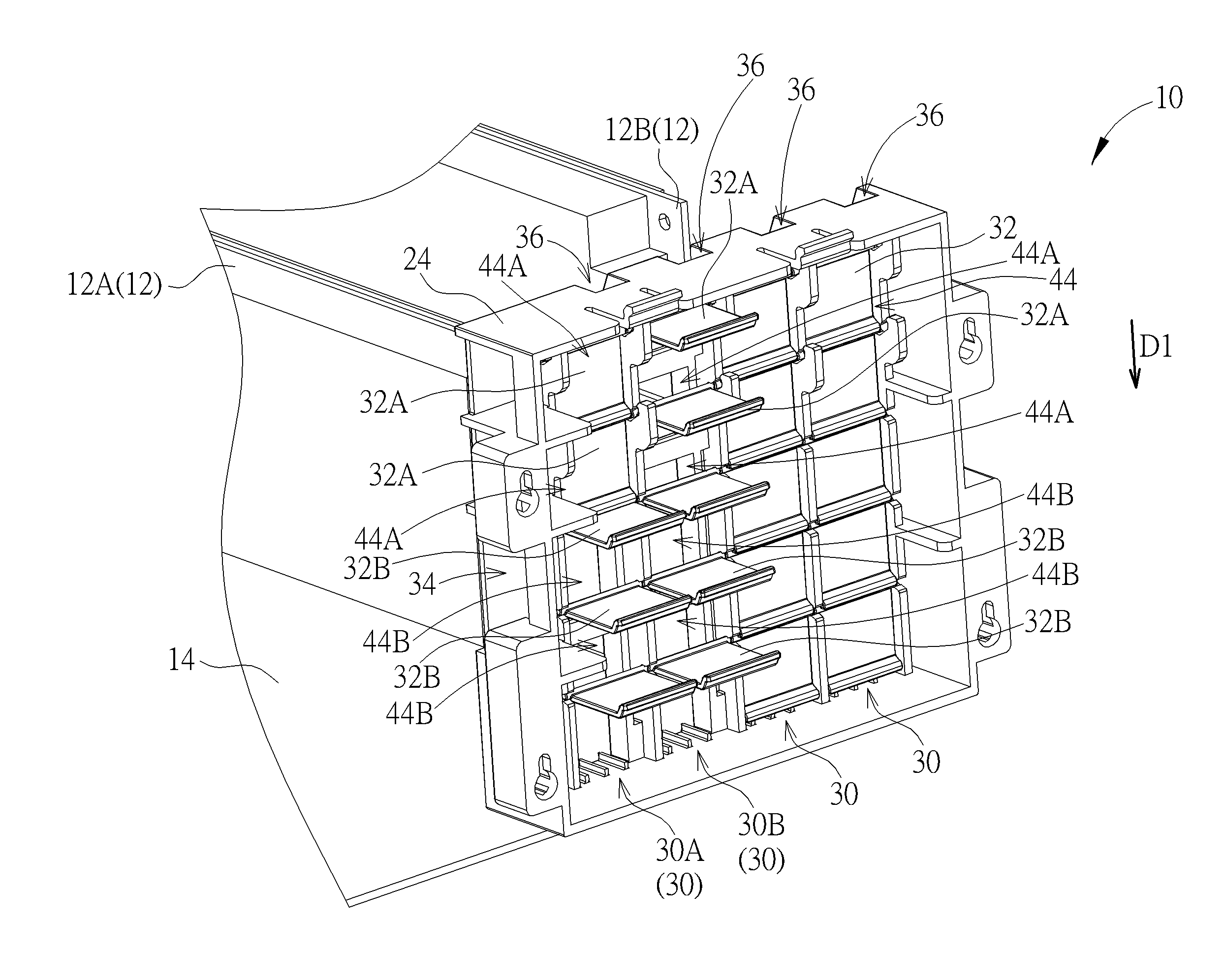
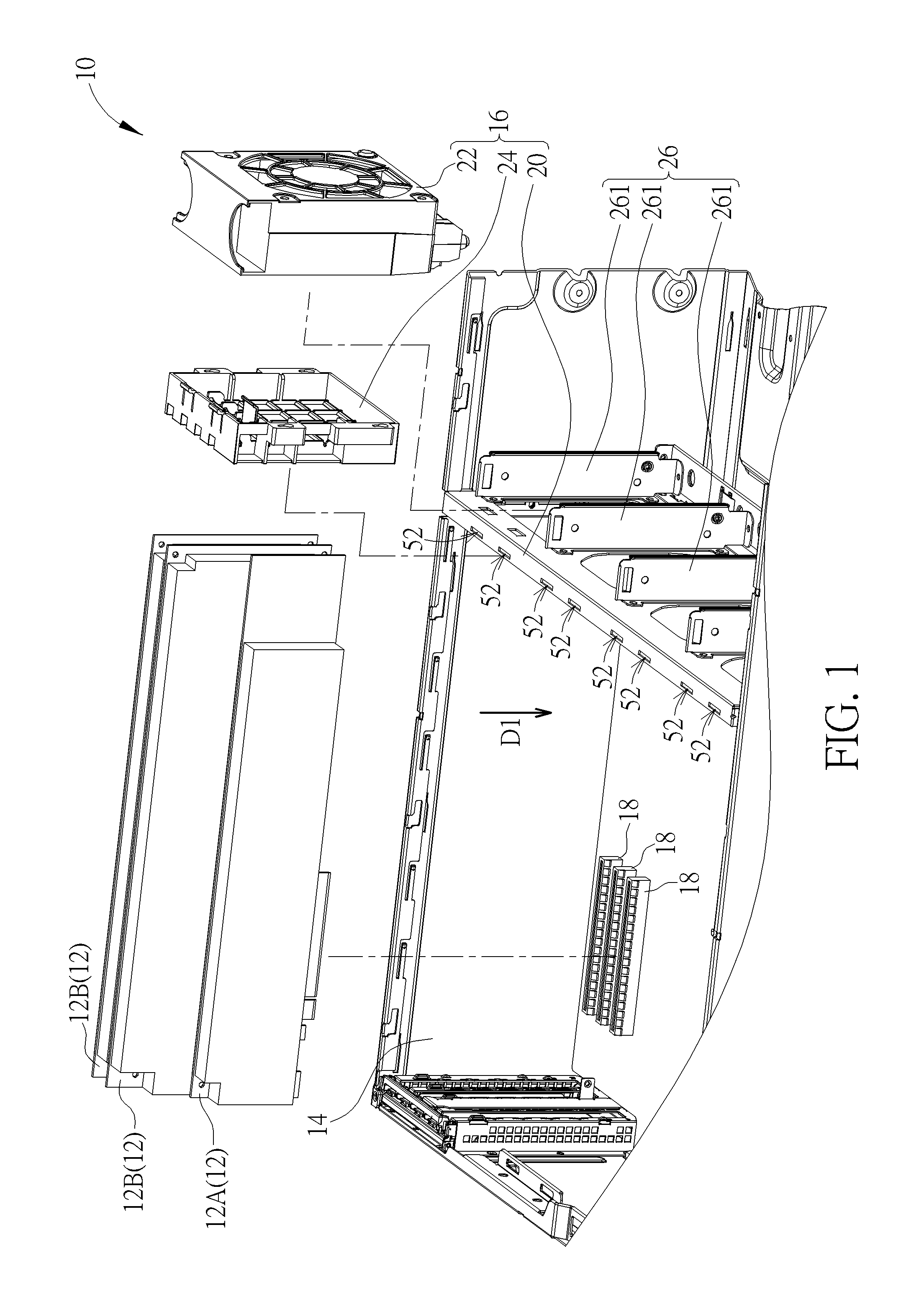
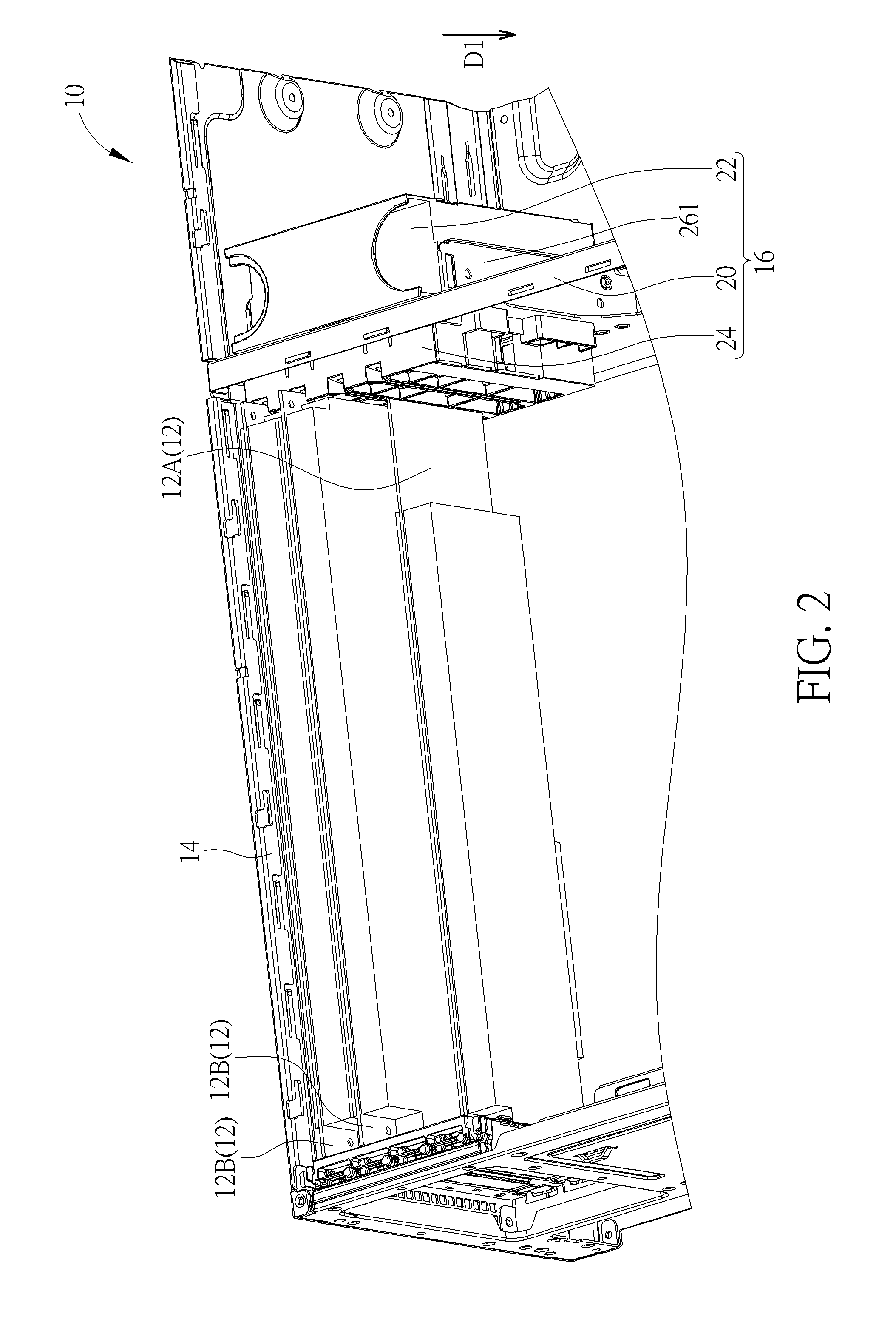
[0032]Please refer to FIG. 1 and FIG. 2. FIG. 1 is an exploded diagram of an electronic device 10 according to an embodiment of the present disclosure. FIG. 2 is an assembly diagram of the electronic device 10 according to the embodiment of the present disclosure. The electronic device 10 is suitable to dispose an interface card 12 optionally. An amount of the interface card 12 is not limited to and the interface card 12 can be a half-height interface card 12A or a full-height interface card 12B. The electronic device 10 includes a base 14 and a heat dissipating module 16. The base 14 is a housing of the electronic device 10, and has several sockets 18 whereto the interface card 12 can be connected. The heat dissipating module 16 includes a frame 20, a flow generating unit 22 and a flow guiding mechanism 24. The frame 20 is disposed inside the base 14 to be a positioning component where the flow generating unit 22 and the flow guiding mechanism 24 are installed. The frame 20 include...


PUM


Abstract

A flow guiding mechanism with flow channel adjusting function is suitable to a heat dissipating module and an electronic device with an interface card. The flow guiding mechanism includes a supporting component, at least one ventilative structure and a plurality of sheltering components. The interface card is assembled with the supporting component in an assembly direction. The ventilative structure includes a plurality of openings, and the plurality of openings is formed on the supporting component in the assembly direction. The plurality of sheltering components is rotatably disposed on the supporting component. One of the plurality of sheltering components covers a corresponding opening of the plurality of openings while the interface card does not contact the foresaid sheltering component, and the interface card rotates the foresaid sheltering component relative to the supporting component to expose the corresponding opening while the interface card is assembled with the supporting component.

Description

BACKGROUND OF THE DISCLOSURE[0001]1. Field of the Disclosure[0002]The present disclosure relates to an electronic device having heat dissipating function, and more particularly, to a flow guiding mechanism with flow channel adjusting function and a related heat dissipating module and an electronic device having the flow guiding mechanism.[0003]2. Description of the Prior Art[0004]Operational efficiency and function of an electronic product are increased with the advanced technology, and the electronic product usually has a plurality of expansion cards to conform to application demand. Heat generated by the computer device is accordingly increased since an amount of the expansion card increases and operational efficiency of the expansion card is enhanced. The computer device includes a fan unit disposed inside the casing to generate flow to cool the expansion card, so as to dissipate the heat generated by the computer device and to prevent the computer device from crash. The conventi...

Claims


Application Information

Patent Timeline
IPC IPC(8): G06F1/20H05K7/20
CPCH05K7/20145G06F1/20H05K7/20181
Inventor CHO, SHIH-HUAILU, KUAN-HSUN
Owner WISTRON CORP
Why Eureka
Try Eureka