Internal combustion engine with auxiliary steam power recovered from waste heat

a technology of waste heat and combustion engine, which is applied in the direction of steam engine plants, machines/engines, mechanical equipment, etc., can solve the problems of increasing fuel prices and shortages, increasing the size, weight and expense of power plants, and increasing air pollution problems. , to achieve the effect of reducing waste heat, reducing fuel consumption, and reducing fuel consumption

Active Publication Date: 2011-08-16
THERMAL POWER RECOVERY
View PDF62 Cites 26 Cited by
  • Summary
  • Abstract
  • Description
  • Claims
  • Application Information

AI Technical Summary

Benefits of technology

[0025]Briefly, one aspect of the invention concerns a composite internal combustion engine suited for use in a vehicle that includes an expandable combustion chamber for burning fuel to power a piston by combustion as well as an expandable chamber within the same engine that is powered by steam generated from what would have been waste combustion heat given off by the internal combustion engine. In the preferred embodiments to be described, there is a combustion chamber that can be hemispherical above each piston that acts on the upper surface of the piston and a steam expansion chamber within the cylinder adjacent the bottom portion of the piston and below the combustion chamber with a steam valving arrangement adjacent a heated engine surface that makes it possible to achieve high efficiencies which surpass what is known as the uniflow steam engine to provide additional power from waste combustion heat; an efficiency level much higher than in an ordinary counterflow steam engine as well as the flexibility needed under non-uniform boiler pressure and engine load conditions that occur in vehicles through a provision for variable steam displacement. Another aspect of the invention concerns a more efficient way of recovering combustion heat that is contained in the combustion engine coolant and in the I.C. exhaust gas using an exhaust powered boiler as well as by direct conduction of the heat produced in the combustion chamber to expanding steam within a steam chamber that is adjacent to the piston. Another aspect of the invention concerns an improved heat recovery, heat exchange, and boiler system for generating steam with a way to better construct a steam expansion chamber, steam cylinder head, heated steam exhaust area and steam supply arrangement that is able to act on a piston within an I.C. engine so as to more effectively economize on fuel, make a more efficient combined gas and steam engine, balance the steam displacement with the boiler output to use steam more efficiently and provide other features that will be apparent from the following description.

Problems solved by technology

Meanwhile, increasing fuel prices and shortages mount steadily as world supplies dwindle and air pollution problems continue.
This arrangement adds considerably to the size, weight and expense of the power plant as well as placing limitations on thermal recovery.
Because of space constraints in a vehicle, the volume and weight of the complete unit is critical.
This robs the engine of power that would otherwise be available by reducing the mean effective cylinder pressure of the incoming charge of steam.
A double acting hollow piston uniflow engine in described in Marks Standard handbook for Mechanical Engineers, 1987 Section 9-37 but is unsuited for use as a combination internal combustion and steam car engine in part due to overheating of the piston.
However, it is also necessary to prevent burnt I.C. gas / oil and blow-by gas from contaminating the steam and thereby reducing boiler and condenser efficiency.

Method used


Image

  • Internal combustion engine with auxiliary steam power recovered from waste heat
  • Internal combustion engine with auxiliary steam power recovered from waste heat
  • Internal combustion engine with auxiliary steam power recovered from waste heat

Examples


Embodiment Construction

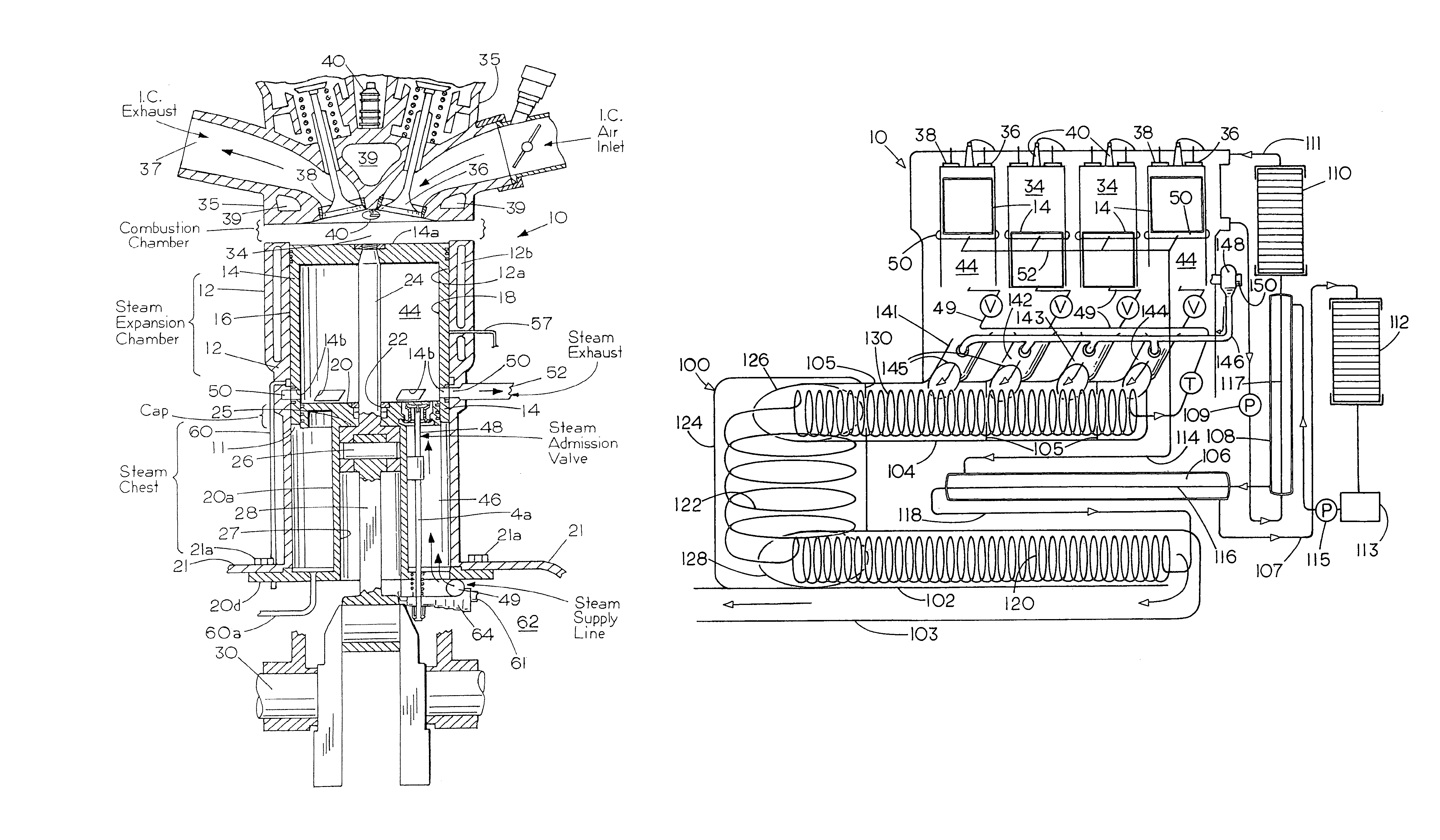
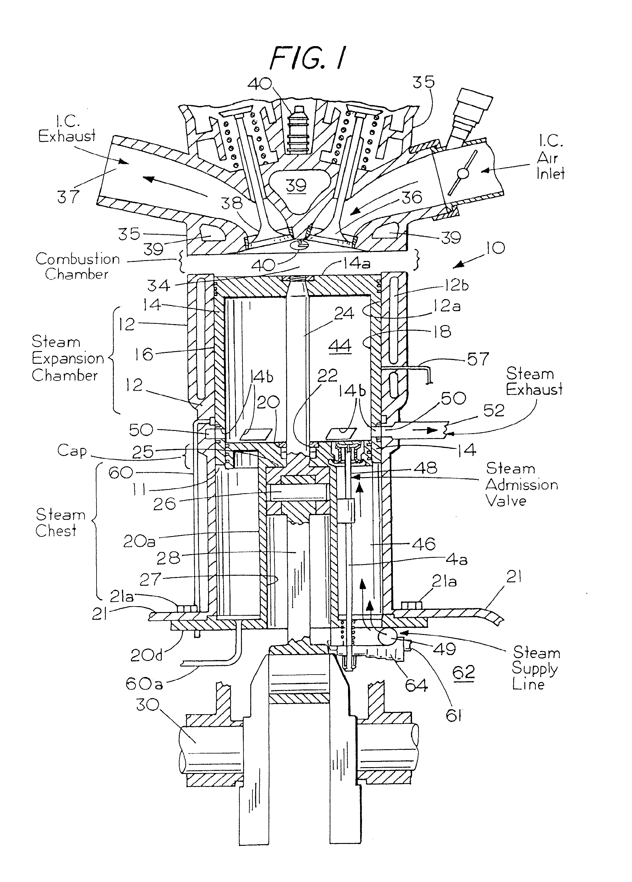
[0026]Refer now to the drawings. Shown diagrammatically in FIGS. 1-8 is a combination internal combustion engine and steam engine 10 that has a cylinder 12 containing a cup shaped trunk style piston 14 which, unlike ordinary pistons, is machined and ground to precise tolerances both outside at 16 as well as in the inside at 18 and is positioned to reciprocate within an annular space 11 between the inside wall 12a of the cylinder 12 and a stationary steam cylinder head.

[0027]The steam cylinder head which is located within the piston 14 comprises a flat hub, disk or circular cap 20 that may be, say, ¼ to ½ inch in thickness supported at the free upper end of an integral crosshead guide column 20a which is secured to the crankcase 21 by bolts 21a (FIGS. 1 and 2) that extend into openings 21b (FIG. 6) in base 20d shown at the lower end of column 20a in FIGS. 1, 2 and 6. The disk or cap 20 acts as a top or end cap for the guide column 20a as well as one end of a steam chamber 44 and has ...


PUM


Abstract

A combination internal combustion and steam engine includes a cylinder having a piston mounted for reciprocation therein with an internal combustion chamber and a steam chamber in the cylinder adjacent the piston and at least one steam exhaust port positioned to communicate with the steam chamber through the wall of the cylinder for exhausting steam at a location in the cylinder wall adjacent to an engine cylinder cap surface that is heated externally to assist in reducing chilling or condensation of steam entering the steam chamber from a boiler fired by waste combustion heat. The invention also permits steam admitted from a steam chest jacketing the cylinder cap to be exhausted from the engine when the steam chamber is in an expanded state whereupon residual steam is then recompressed prior to admitting the next charge of steam with the stream in the steam chamber being heated directly by the combustion chamber as well as by heat from the steam chest. An I.C. exhaust powered heater is a part of an I.C. exhaust manifold which functions as an afterburner with supplemental air injection for promoting combustion of unburned exhaust constituents to superheat steam that is piped through it to the steam chest. The invention provides valves for balancing steam engine displacement with boiler output and for cylinder compounding with a boiler, heat exchange and control arrangement for efficiently recovering waste heat.

Description

[0001]Applicants claim the benefit of provisional application Ser. No. 60 / 905,732 filed Mar. 7, 2007 and bearing the same title which is incorporated herein by reference.FIELD OF THE INVENTION[0002]This invention relates to internal combustion engines with steam power obtained from waste combustion heat and to a combination internal combustion (I.C.) engine and steam engine.BACKGROUND[0003]Internal combustion engines although highly developed, dependable and relied upon for almost all road transportation throughout the world generally lose about 72-75% of the fuel heating value through radiation, engine coolant and exhaust. The measured brake horsepower of a typical six-cylinder spark ignition automobile was only 21% of the fuel heating value at 72 MPH and only 18% at 43 MPH, Internal Combustion Engine Fundamentals, J. B. Heywood, McGraw Hill 1988 pg. 675. Meanwhile, increasing fuel prices and shortages mount steadily as world supplies dwindle and air pollution problems continue. Wh...

Claims


Application Information

Patent Timeline
Patent Type & Authority Patents(United States)
IPC IPC(8): F01K23/06F01K27/00F01K23/10F01K13/00F02G3/00
CPCF01K11/00F01K21/02Y02E20/14Y02T10/16F01K23/06F01K19/06F01K27/00F02B75/40Y02T10/12
Inventor HARMON, SR., JAMES V.HARMON, JR., JAMES V.HARMON, STEPHEN C.
Owner THERMAL POWER RECOVERY
Why Eureka
Try Eureka