
Ball joint for a washing machine suspension system

Active Publication Date: 2016-10-20
HAIER US APPLIANCE SOLUTIONS INC
View PDF8 Cites 6 Cited by
  • Summary
  • Abstract
  • Description
  • Claims
  • Application Information

AI Technical Summary

Benefits of technology

This patent describes a suspension system for a washing machine that includes a frame member and a suspension rod. The frame member has a curved joint recess with a rod opening, and the suspension rod is supported by the frame member through a ball joint that moves vertically. The ball joint has a lower portion with a curved profile that fits into the joint recess. The joint body has lubrication inlet and channels to allow lubricant to flow around the outer surface and the interface between the joint recess and the lower portion of the joint body. The technical effect of this invention is to improve the stability and smooth operation of the washing machine's suspension system.

Problems solved by technology

Unfortunately, such pre-application of the lubricant typically requires the use of assembly aids or other assembly features to keep other components away from the pre-lubricated joint cup as an the operator assembles the components.

Method used


Image

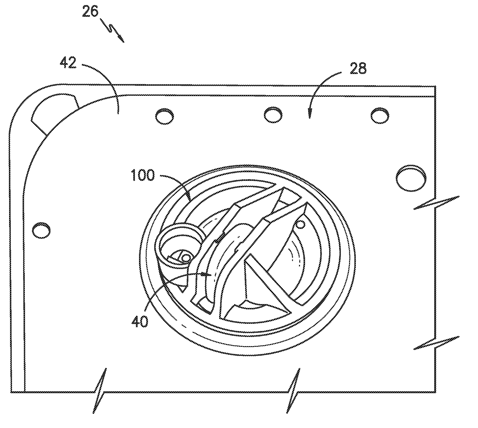
  • Ball joint for a washing machine suspension system
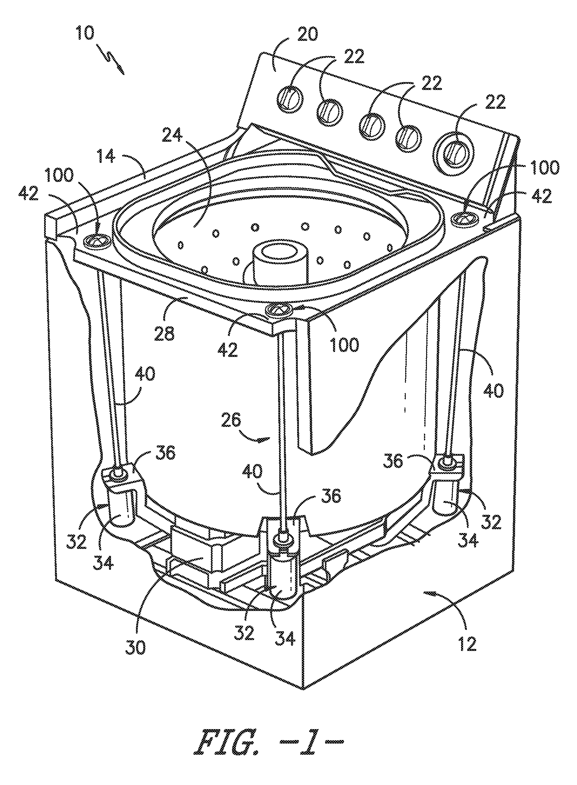
  • Ball joint for a washing machine suspension system
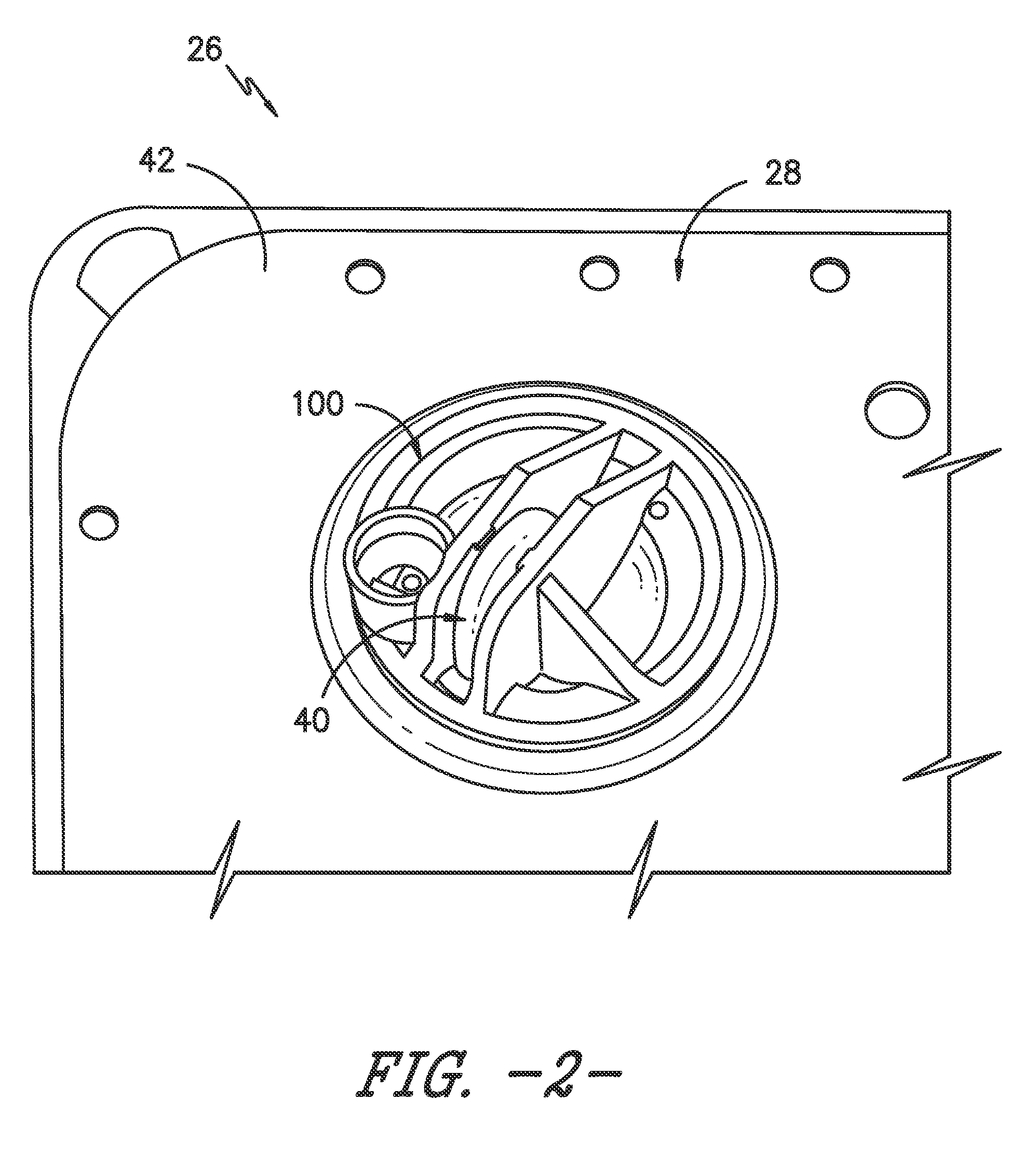
  • Ball joint for a washing machine suspension system

Examples


Embodiment Construction

[0019]Reference now will be made in detail to embodiments of the invention, one or more examples of which are illustrated in the drawings. Each example is provided by way of explanation of the invention, not limitation of the invention. In fact, it will be apparent to those skilled in the art that various modifications and variations can be made in the present invention without departing from the scope or spirit of the invention. For instance, features illustrated or described as part of one embodiment can be used with another embodiment to yield a still further embodiment. Thus, it is intended that the present invention covers such modifications and variations as come within the scope of the appended claims and their equivalents.

[0020]In general, the present subject matter is directed to an improved ball joint design to be used within a suspension system for a washing machine. Specifically, in several embodiments, the ball joint includes various lubrication features for allowing a ...


PUM


Abstract

A ball joint for use within a washing machine suspension system may generally comprise a joint body including a lower portion and an upper portion. The lower portion may define an outer surface having a curved profile. In addition, the joint body may define at least one lubrication inlet port extending between the upper and lower portions and at least one lubrication channel extending circumferentially around at least a portion of the lower portion along the outer surface. The lubrication channel(s) may be in fluid communication with the lubrication inlet port(s) such that, when a lubricant is injected into the lubrication inlet port(s) at the upper portion of the joint body, the lubricant flows from the lubrication inlet port(s) into the lubrication channel(s) and then flows circumferentially within the lubrication channel(s) along the outer surface.

Description

FIELD OF THE INVENTION[0001]The present subject matter relates generally to washing machines and, more particularly, to an improved ball joint design for a washing machine suspension system that allows the joint to be lubricated post assembly of the suspension system.BACKGROUND OF THE INVENTION[0002]Conventional washing machines typically include a suspension system for suspending a wash tub and other components, such as a basket, a motor, and a transmission, within a cabinet and for damping movement of the wash tub and the basket. Known suspension systems include an upper frame and a lower frame. The upper frame is secured to, and supported by, the cabinet. The lower frame is coupled to the upper frame and is movable relative to the upper frame. Typically, the wash tub, basket, motor and transmission are coupled to the lower frame.[0003]Additionally, conventional suspension systems often include suspension rods that extend from the lower frame to the upper frame. Typically, the sus...

Claims


Application Information

Patent Timeline
Patent Type & Authority Applications(United States)
IPC IPC(8): D06F37/26F16C11/06
CPCD06F37/268F16C11/0695F16C11/068D06F37/24D06F39/12F16C11/0604F16C33/102F16C2340/00Y10T403/32631
Inventor COXON, DAVID JOHN
Owner HAIER US APPLIANCE SOLUTIONS INC
Learn More