Screw Machine

Active Publication Date: 2016-11-10
MAN ENERGY SOLUTIONS SE
View PDF4 Cites 0 Cited by
  • Summary
  • Abstract
  • Description
  • Claims
  • Application Information

AI Technical Summary

Benefits of technology

[0009]According to one aspect of the invention, the control slide, when shifting out of the rotor housing portion into the outflow housing portion, is not only guided on the rotor housing side but additionally also on the outflow housing side, namely by way of a positively joined guide of the outflow housing portion for the control slide. In particular when the control slide is shifted far out of the rotor housing portion into the outflow housing portion a shifting of the control slide, which would result in a collision of the same with the screw rotors, can be safely and reliably prevented.
[0010]According to an advantageous further development, the positively joined guide of the outflow ho

Problems solved by technology

This can result in the control slide, at its end projecting into the outflow housing portion, shift

Method used


Image

  • Screw Machine
  • Screw Machine
  • Screw Machine

Examples


Embodiment Construction

[0016]The present invention relates to a screw machine, in particular a screw compressor.

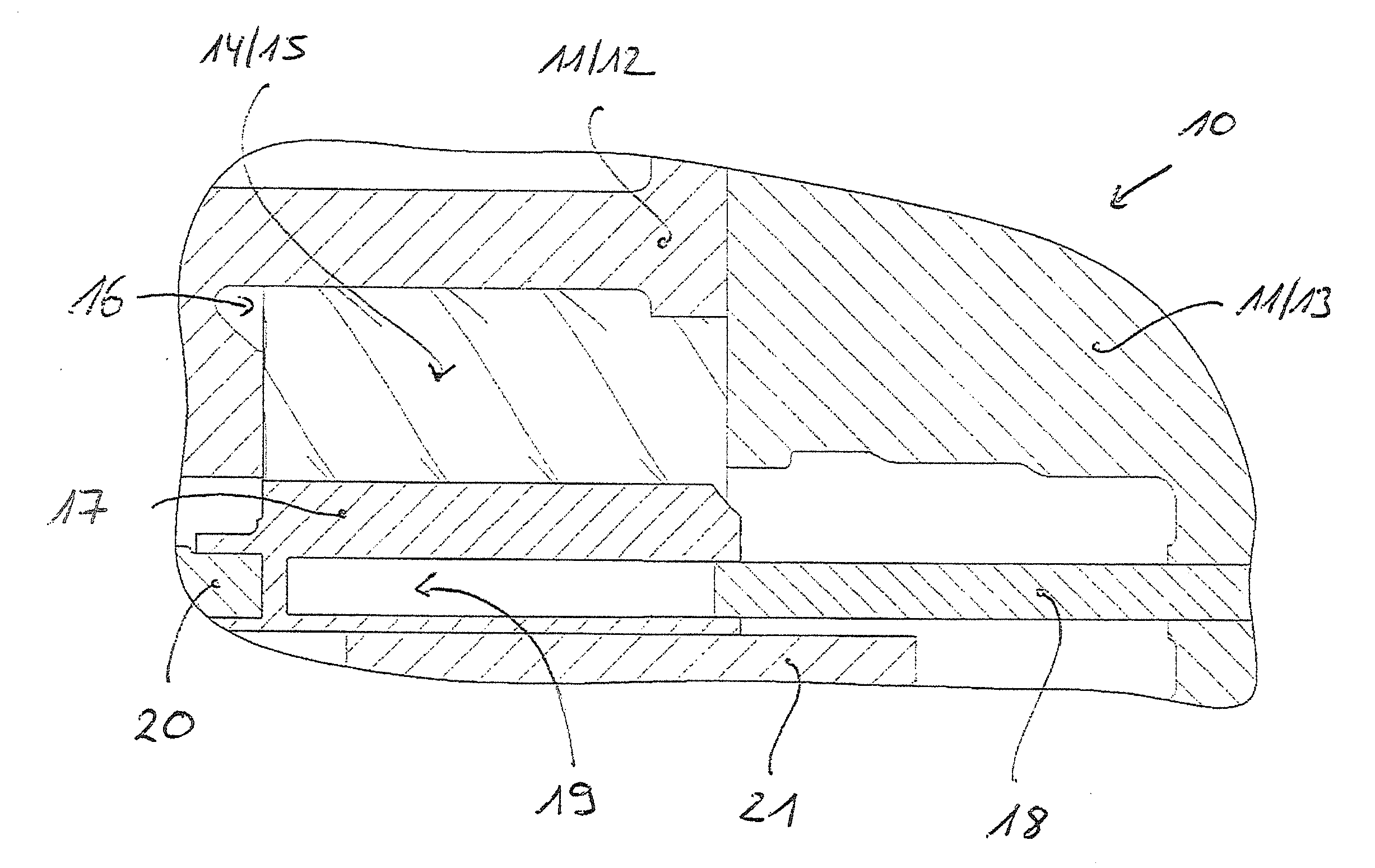
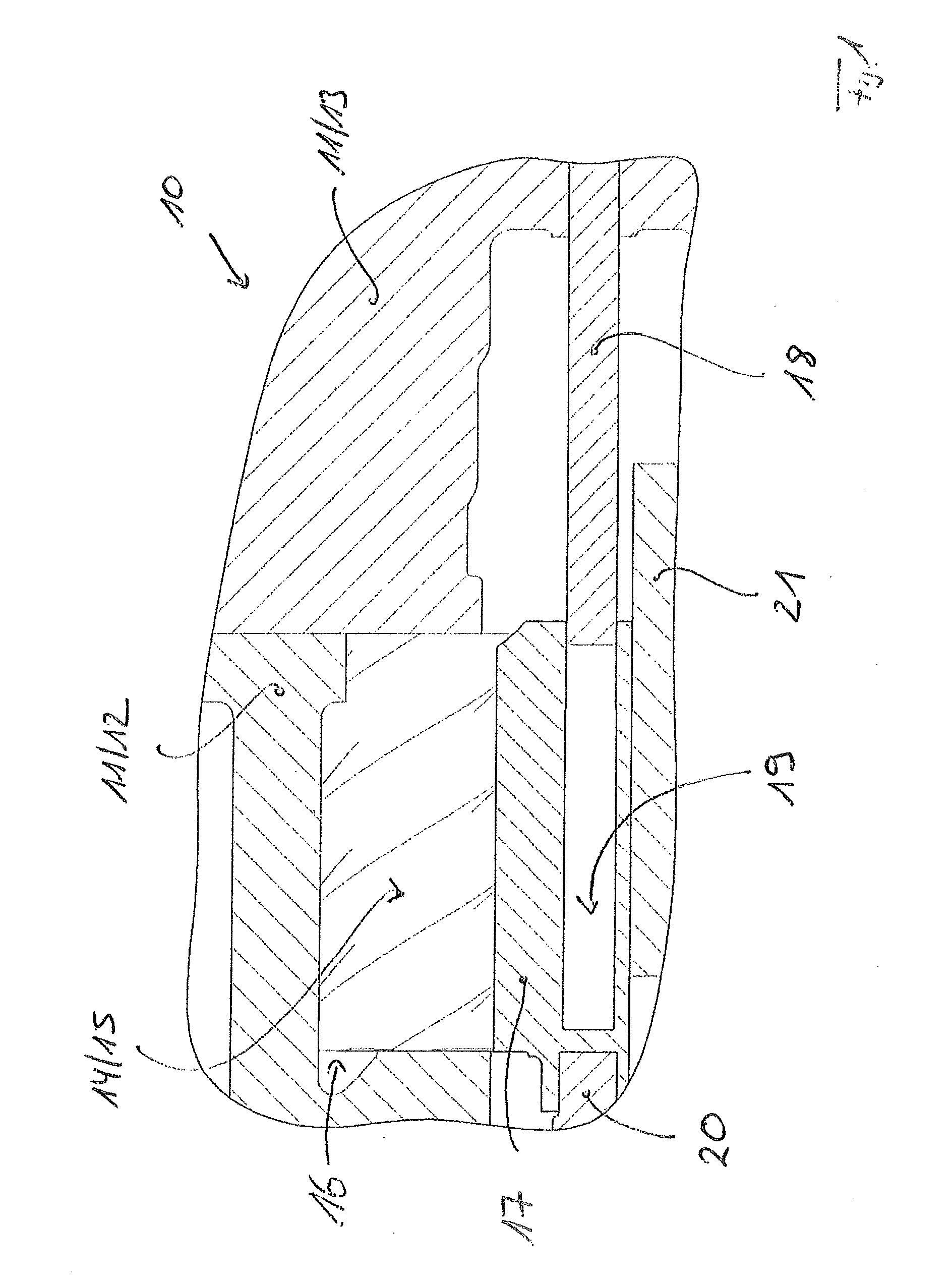
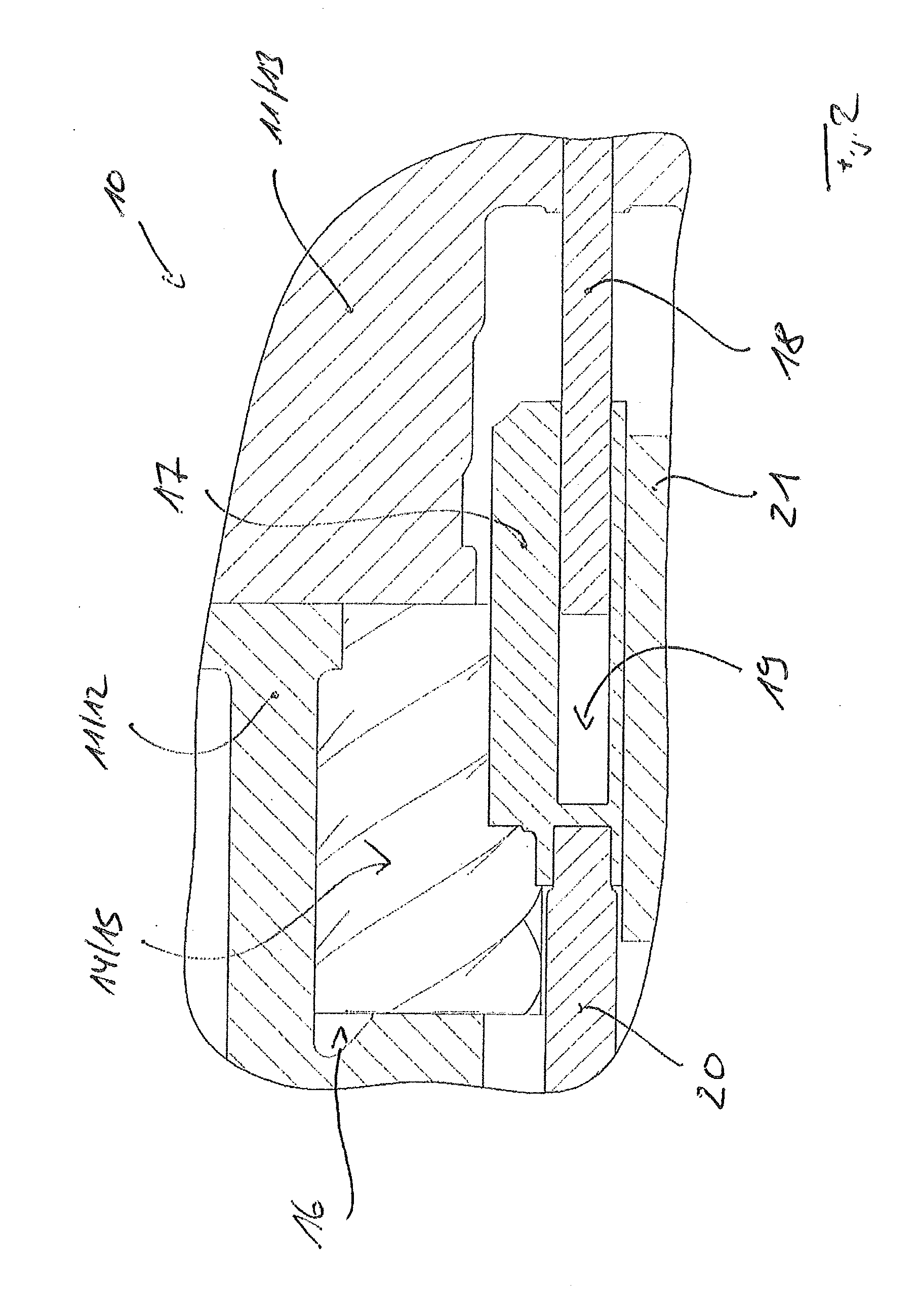
[0017]FIG. 1 to 3 each show cross section through a screw machine which is embodied as a screw compressor 10. The screw compressor 10 comprises a compressor housing 11, which comprises a rotor housing portion 12 and an outflow housing portion 13. The compressor housing 11, consisting of the rotor housing portion 12 and the outflow housing portion 13, which can be designed both in one part and also in multiple parts.

[0018]The screw compressor 10 furthermore comprises screw rotors 14, 15, rotatably mounted in the rotor housing portion 12 of the screw compressor 10 that form a pair of screw rotors 14, 15.

[0019]The rotor housing portion 12 together with a control slide 17 mounted in the rotor housing portion 12 defines a working space or compression space 16, in which a medium to be compressed is compressed by the screw rotors 14, 15. In the Figures, the control slide 17 defines the working space or...


PUM


Abstract

A screw machine having a rotor housing portion and an outflow housing portion, screw rotors mounted in the rotor housing portion that form a rotor pair, and a control slide that is likewise mounted in the rotor housing portion, which delimits a working space of the rotor housing portion and which can be shifted parallel to the rotor axes of the screw rotors to change a size of the effective working space. The control slide, when shifted out of the rotor housing portion into the outflow housing portion, is guided by a positively joined guide of the outflow housing portion.

Description

BACKGROUND OF THE INVENTION[0001]1. Field of the Invention[0002]The invention relates to a screw machine, in particular a screw compressor.[0003]2. Description of the Related Art[0004]The fundamental construction of screw machines designed for example as screw compressors is familiar to the person skilled in the art. Accordingly, a screw compressor comprises a machine housing or a compressor housing, which comprises a rotor housing portion and an outflow housing portion. In the rotor housing portion, screw rotors are mounted that form a rotor pair and serve for compressing a medium to compressed. Likewise, a control slide is mounted in the rotor housing portion, which in portions delimits a working space or a compression space of the rotor housing portion and for changing the size of the effective working space or effective compression space is shiftable parallel to the rotor axes of the screw rotors.[0005]Accordingly, a screw compressor is known from DE 103 26 466 A1 with screw rot...

Claims


Application Information

Patent Timeline
IPC IPC(8): F04C28/10F04C18/16
CPCF04C18/16F04C28/10F04C28/12
Inventor LEHMANN, TIMTEWES, NORBERTWENNEMAR, JURGEN
Owner MAN ENERGY SOLUTIONS SE
Why Eureka
Try Eureka