Device for centering and guiding a drill bit of a dental handpiece

Active Publication Date: 2010-12-09
ANTHOGYR
View PDF14 Cites 45 Cited by
  • Summary
  • Abstract
  • Description
  • Claims
  • Application Information

AI Technical Summary

Benefits of technology

[0055]Such spring means make it possible to position the guide sleeve reliably from the beginning of drilling without intervention by the practitioner. This efficiently limits any risk of the drill bit coming into contact with the jawbone of the patient without being appropriately guided.
[0056]Such spring means also make it possible, during axial withdrawal of the drill bit from the jaw of the

Problems solved by technology

The problem arises that, when drilling the jawbone of the patient to fit an implant, the practitioner uses in succession a plurality of drill bits of different diameters driven in rotation by the dental handpiece to make firstly a hole of small diameter that is then enlarged up to the nominal diameter of the implant to be fitted, which generally corresponds to the diameter of the interior bore of the tubular drilling bush, namely 4.2 mm or 5.2 mm, for example, for those most widely used.
Such a solution has the drawback of increasing the number of parts necessary and obliges dental equipment manufacturers to use color codes to assist the practitioner to distinguish between the different sizes of tubular guide sleeve.
However, there remains a risk of a practitioner using a tubular guide sleeve with an internal bore of greater diameter than th

Method used


Image

  • Device for centering and guiding a drill bit of a dental handpiece
  • Device for centering and guiding a drill bit of a dental handpiece
  • Device for centering and guiding a drill bit of a dental handpiece

Examples


example 1

Drilling a Hole in the Jaw of the Patient with a Device of the First Embodiment

[0119]In this example, the following choices are made:

[0120]h1 is made equal to 9 mm,

[0121]L1 is made equal to 5 mm,

[0122]L2 is made equal to 8 mm,

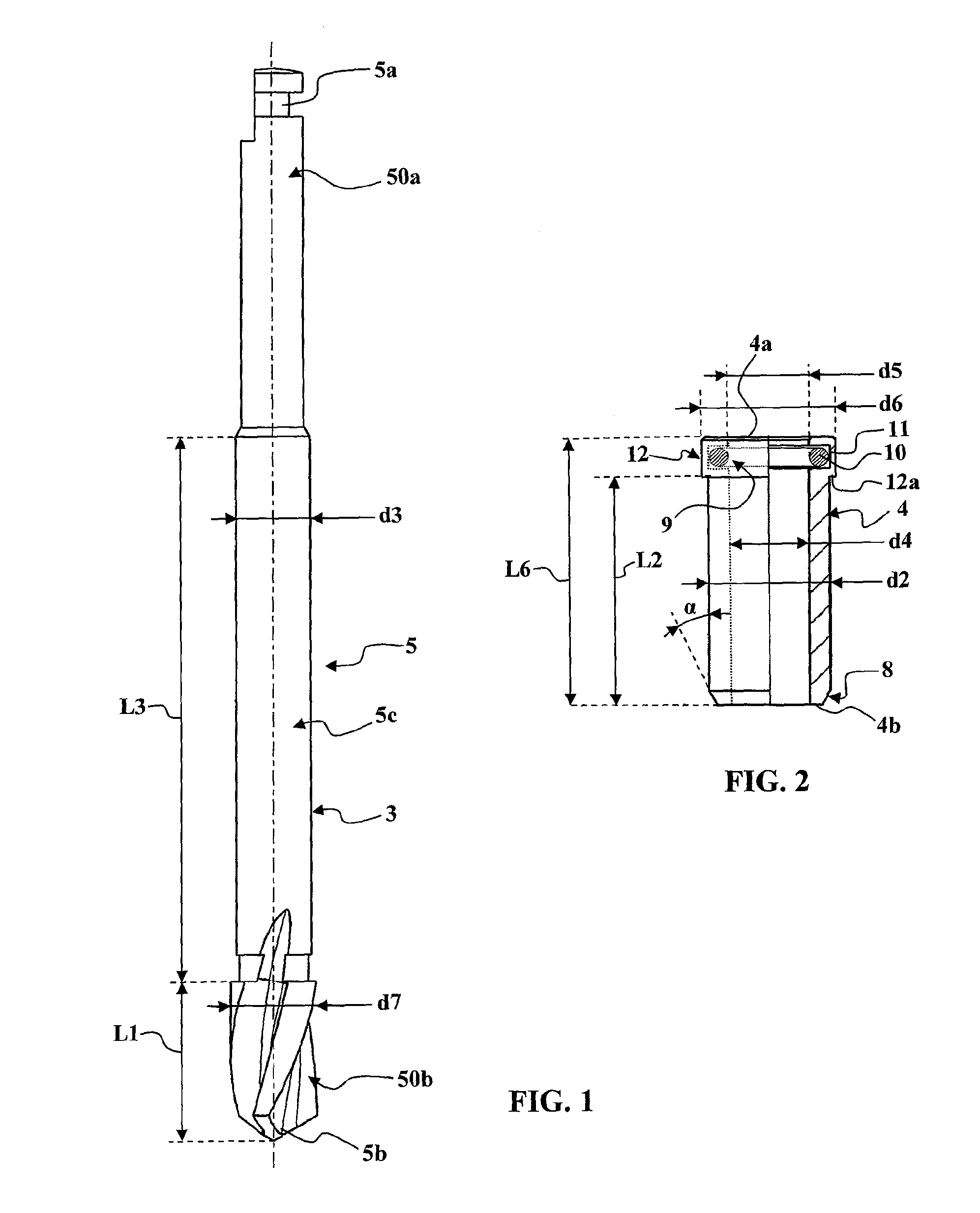
[0123]L3 is made equal to 30 mm,

[0124]L6 is made equal to approximately 10 mm,

[0125]d1 is made equal to 4.2 mm,

[0126]d2 is made equal to 4.17 mm,

[0127]d3 is made equal to 2.8 mm;

[0128]d4 is made equal to 2.8 mm (+clearance),

[0129]d5 is made equal to 2.8 mm (+clearance),

[0130]d6 is made equal to 4.6 mm.

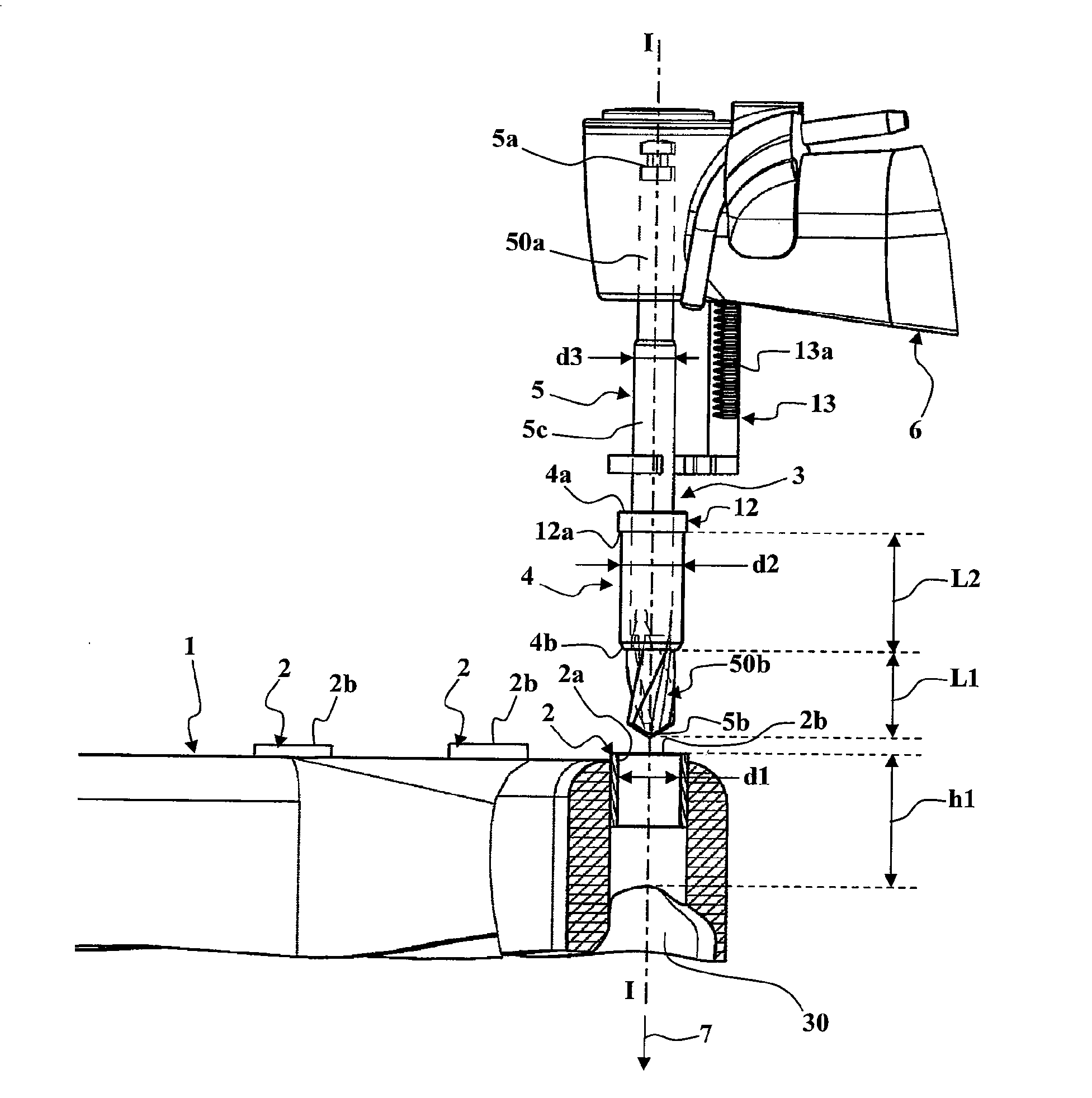
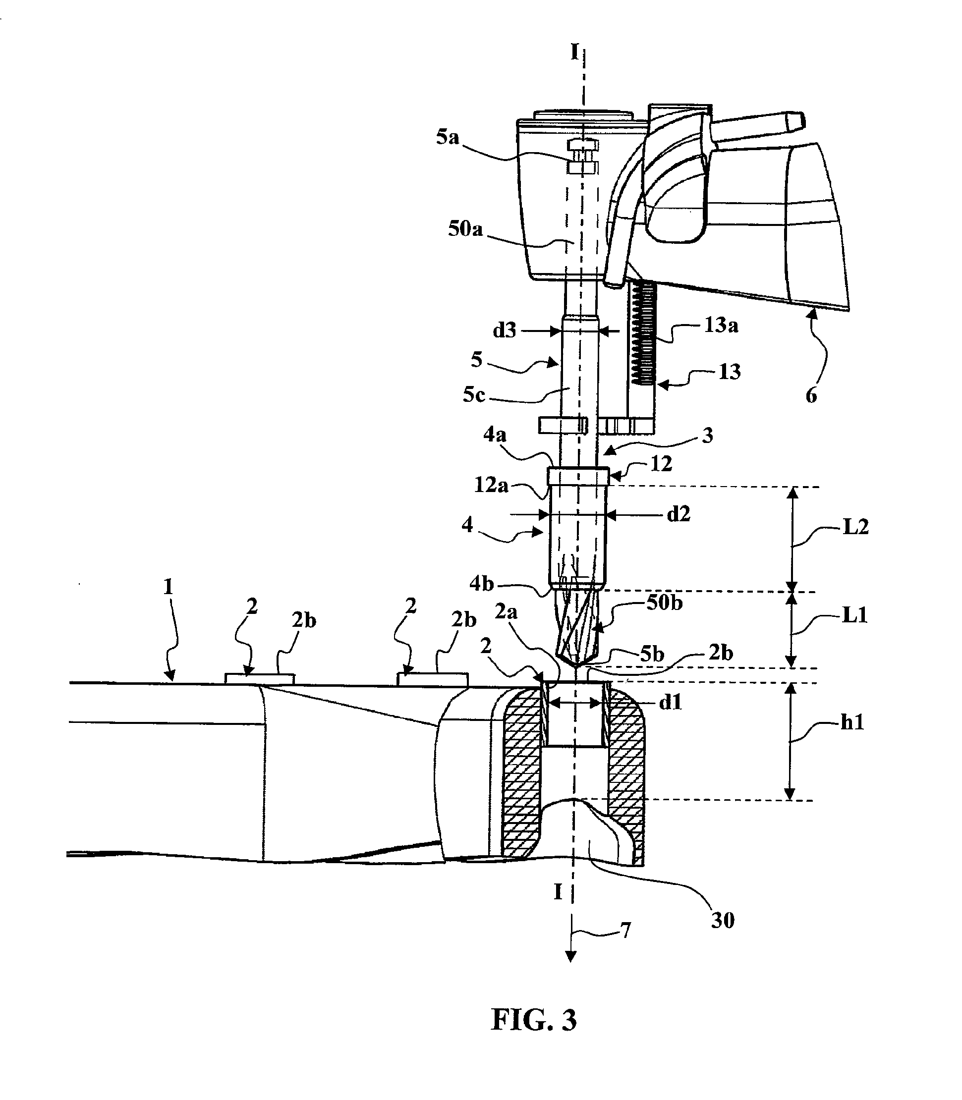
[0131]The practitioner mounts the guide sleeve 4 on the intermediate section 5c with the distal end 4b abutted against the distal cutting section 50b and then fixes the drill bit 5 to the dental handpiece 6 fitted with abutment means 13. The practitioner then adjusts the height of the abutment means 13 to drill a hole of particular depth.

[0132]When the drill bit 5 comes into contact with the jawbone of the patient, the guide sleeve 4 is already engaged in the tubu...

example 2

Adjustment of the Device of the Second Embodiment to Drill a Hole 8 Mm Deep in the Jaw of the Patient

[0159]In this example, the first height h1 is 9 mm, the axial movement allowed by the spring means 15 is 15 mm and the axial length L5 of the guide sleeve 4 is 8 mm.

[0160]To adjust conveniently the axial position of the guide sleeve 4, the practitioner mounts the drill bit 5 and the centering and guiding device of the second embodiment of the invention on the dental handpiece 6.

[0161]The rack of the support rod 19 is immobilized in the receiving sleeve 20 so that, when the spring means 15 are compressed (guide sleeve 4 in high position), the proximal end 4a of the guide sleeve is at a distance from the distal end 5b of the drill bit 5 equal to the sum of the first height h1 and the required depth of the hole (8 mm in this example), that is to say 17 mm here. In the low position, the proximal end 4a of the guide sleeve 4 is therefore offset from the distal end 5b of the drill bit 5 by...

example 3

Adjustment of the Device of the Second Embodiment to Drill a Hole 15 Mm Deep in the Jaw of the Patient

[0162]In this example, the first height h1 is 9 mm, the axial movement allowed by the spring means 15 is 15 mm and the axial length L5 of the guide sleeve 4 is 8 mm.

[0163]In order to adjust conveniently the axial position of the guide sleeve 4, the practitioner mounts the drill bit 5 and the centering and guiding device of the second embodiment of the invention on the dental handpiece 6. The rack of the support rod 19 is immobilized in the receiving sleeve 20 so that, when the spring means 15 are compressed (guide sleeve 4 in high position), the proximal end 4a of the guide sleeve is at a distance from the distal end 5b of the drill bit 5 equal to the sum of the first height h1 and the required depth of the hole (15 mm in this example), i.e. 24 mm here.

[0164]In the low position, the proximal end 4a of the guide sleeve 4 is therefore offset from the distal end 5b of the drill bit 5 b...


PUM


Abstract

A device for centering and guiding at least one drill bit of a dental handpiece when drilling a hole in the jaw of a patient in cooperation with a surgical guide equipped with a tubular drill bushing. A support holds a tubular guide sleeve permanently in a coaxial and sliding position with respect to the drill bit. The tubular guide sleeve is able to engage with slight play in the tubular drill bushing. The support insures the engagement of the guide sleeve in the tubular drill bushing at the latest when the drill bit starts to drill in the patient's jaw, thus insuring the centering and guiding of the drill bit.

Description

TECHNICAL FIELD OF THE INVENTION[0001]The present invention concerns dental implants and more particularly installing dental implants assisted by a surgical guide placed in the mouth of the patient.[0002]To replace damaged teeth in the mouth of a patient, implants fixed into the jawbone of the patient have been used for many years. After drilling a hole in the jawbone of the patient using a dental handpiece, the proximal part of an implant is screwed into the hole after which its distal part receives a dental prosthesis.[0003]To assist the practitioner to produce the holes in the jawbone of the patient, surgical guides have been used for a number of years that the practitioner can fit in the patient's mouth on their jaw. This kind of surgical guide is an arcuate structure that follows the curvature of the jaw and that is provided with one or more tubular drilling bushes that extend as far as the vicinity of the area of the jawbone to be drilled. These surgical guides are produced us...

Claims


Application Information

Patent Timeline
IPC IPC(8): A61C19/04
CPCA61B2019/306A61C8/0089A61C1/084A61B2090/036
Inventor LANCIEUX, CEDRICRICHARD, HERVE
Owner ANTHOGYR
Why Eureka
Try Eureka