Lighting device having a solar panel

Inactive Publication Date: 2016-11-17
CHO JASON YOUNG +1
View PDF6 Cites 2 Cited by
  • Summary
  • Abstract
  • Description
  • Claims
  • Application Information

AI Technical Summary

Benefits of technology

[0007]The solar lighting device, disclosed in the present invention, comprises a lighting device holder; a solar panel; a rechargeable battery; LED lights; and a circuit board. Comparing the solar lighting device in the present invention with other solar lighting devices found in the market place, the solar lighting device of the present invention is m

Problems solved by technology

Further the standalone solar lighting device is one that only use

Method used


Image

  • Lighting device having a solar panel
  • Lighting device having a solar panel
  • Lighting device having a solar panel

Examples


Example

[0038]Reference will now be made in detail to representative embodiments illustrated in the accompanying drawings. It should be understood that the following descriptions are not intended to limit the embodiments to one preferred embodiment. To the contrary, it is intended to cover alternatives, modifications, and equivalents that can be included within the spirit and scope of the described embodiments as defined by the appended claims.

[0039]In the scope of the present invention, sometimes, the solar lighting device is also referred as a solar lamp. In the scope of the present invention, sometimes, the solar cell assembly is also referred to as a solar disk.

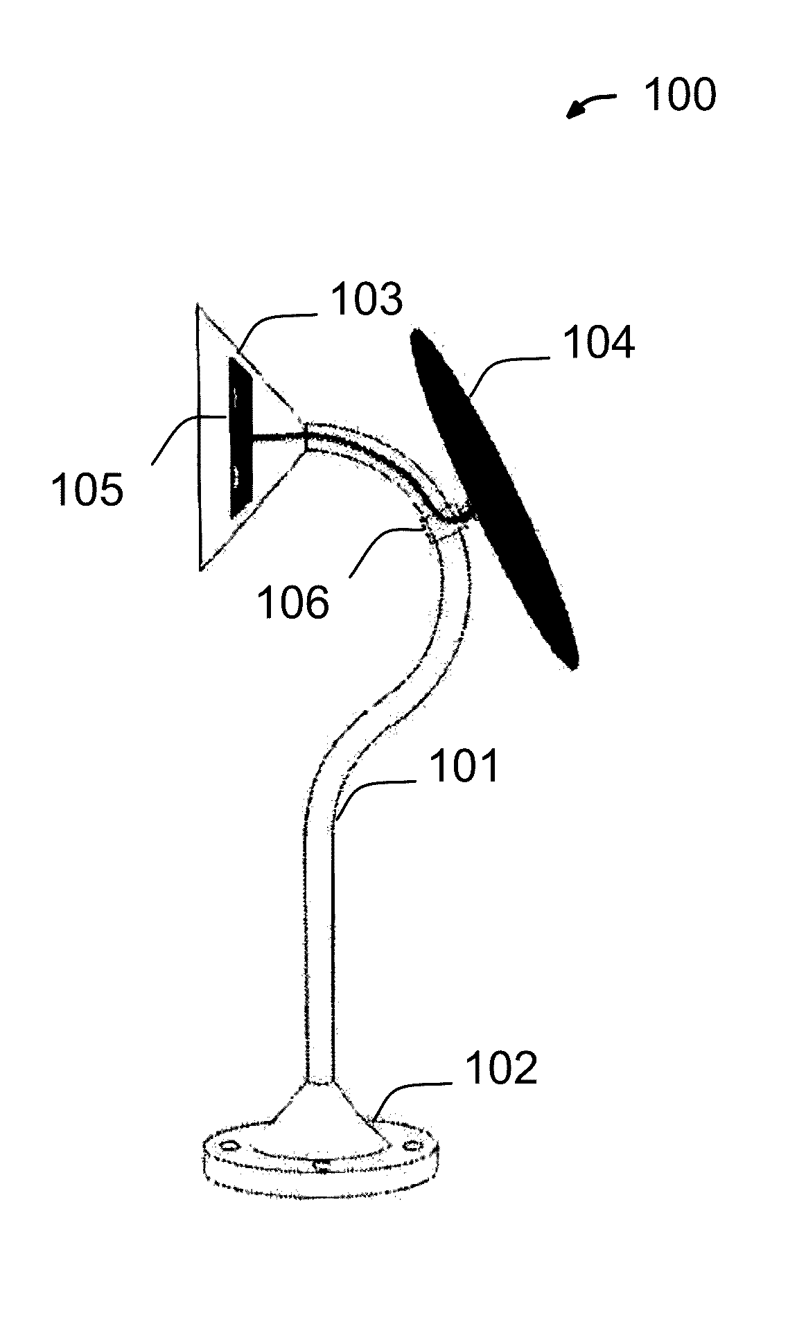
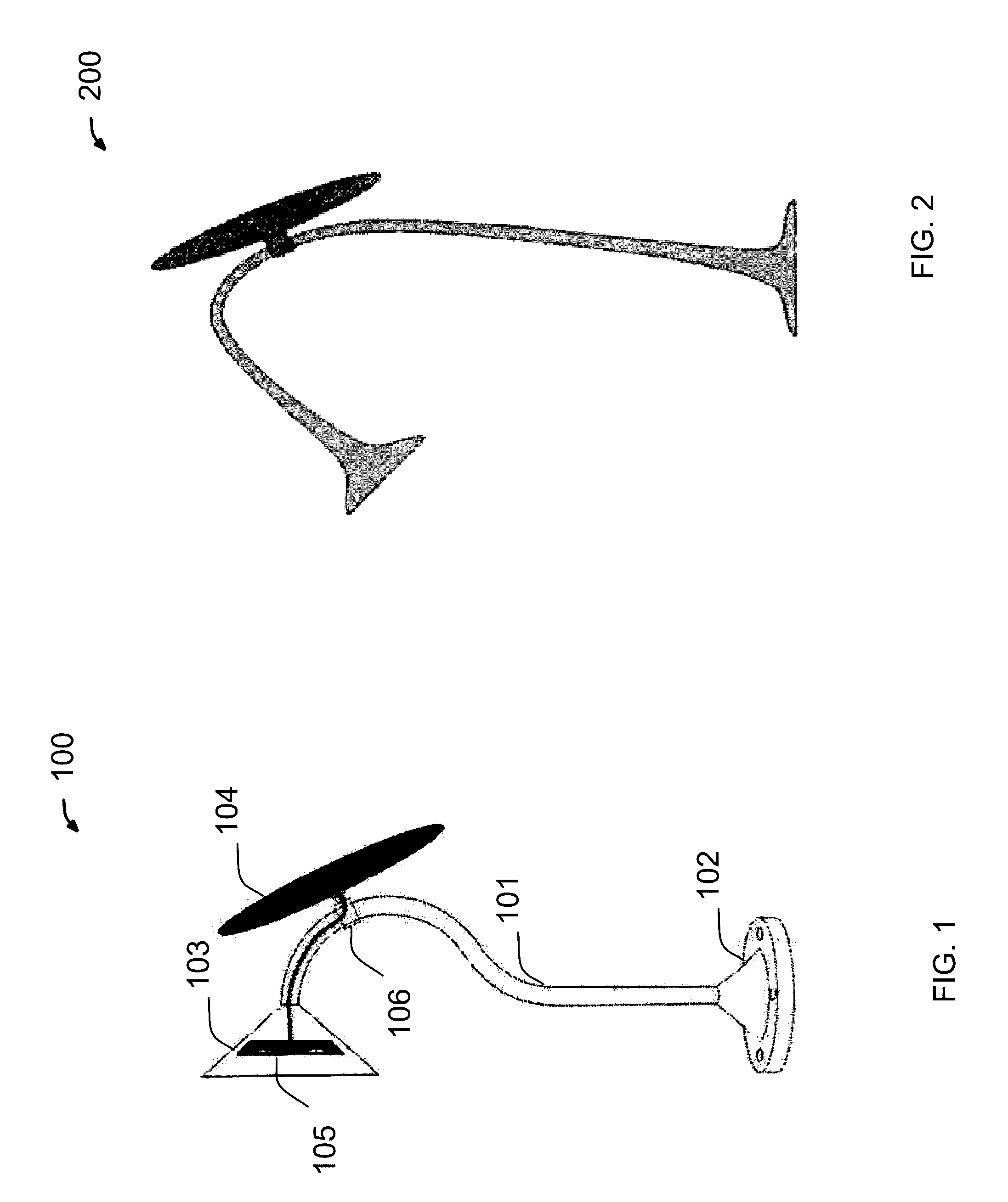
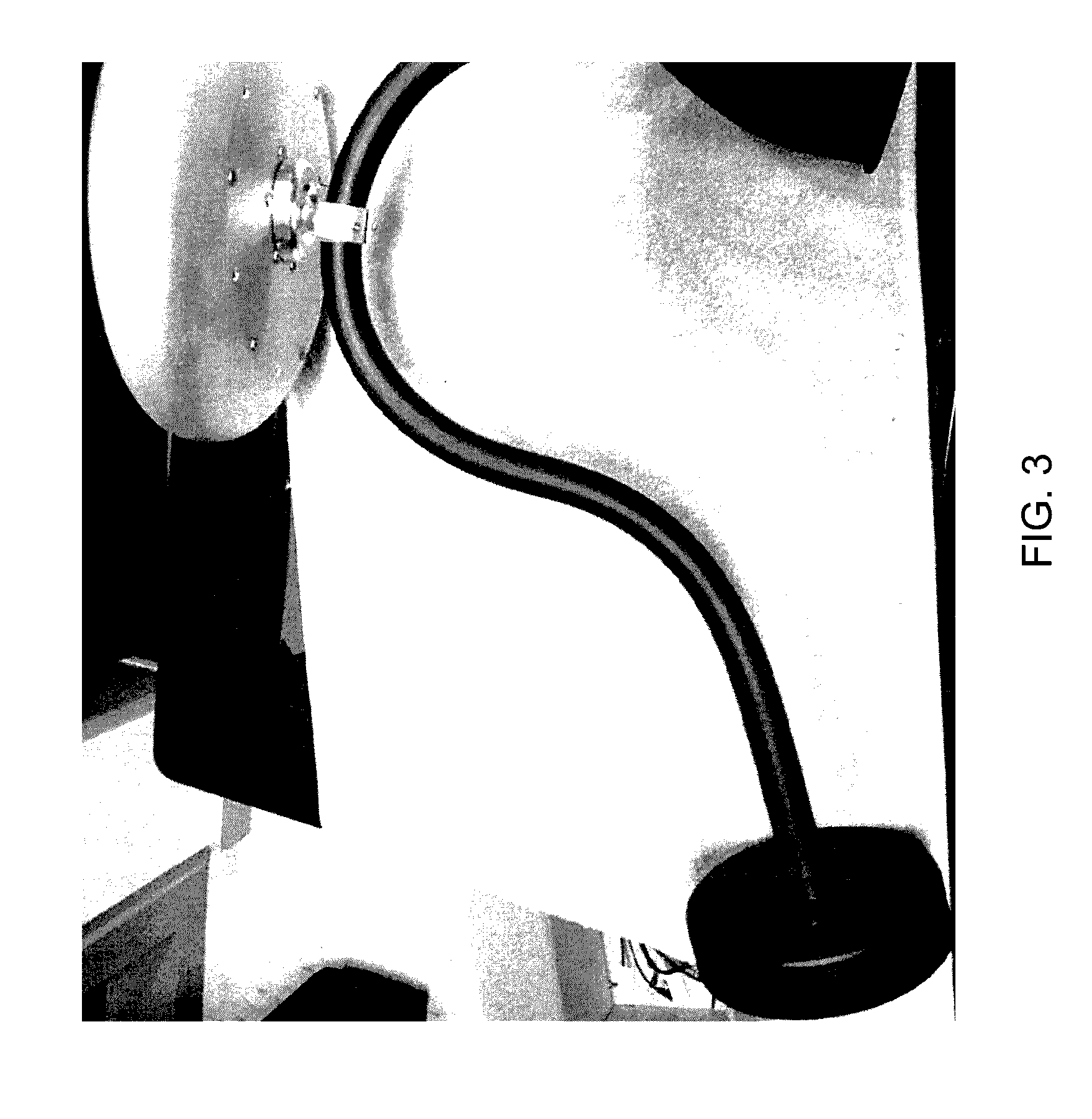
[0040]In the scope of the present invention, referring to FIGS. 1-3, a solar lighting device (100 and 200) is described. The solar lighting device comprises a housing, a solar cell assembly 104, the solar cell assembly 104 is connected to the housing through an attachment assembly 106. The housing of the solar lighting device com...


PUM


Abstract

A solar lighting device, disclosed herein, comprises a solar cell assembly, attached to an elongated lighting device holder through an attachment assembly which can be rotated to provide an orientation of the solar panel so as to harvest more sun light.

Description

TECHNICAL FIELD[0001]The present invention is in the field of solar powered lighting devices. Specifically, the invention relates to a solar powered device, which provides low cost lighting to people with sufficient sunshine to provide long day-light periods, particularly to people with unreliable access to electric power sources.BACKGROUND OF THE INVENTION[0002]Solar energy is believed to be a green energy and clean energy alternative for oil and gas. However, as it stands today, it only represents a tiny portion of the total energy used in the United States. Until recently, with the technology advancements in photovoltaic cell efficiency and the high-output and low-cost manufacturing processes available, more and more photovoltaic powered consumer goods have become commercially available.[0003]One challenging aspect of using solar cells to power consumer electronics, is the available hours of daylight time. For example, with the efficiency of the current silicon based solar cells,...

Claims


Application Information

Patent Timeline
IPC IPC(8): F21S9/03F21V21/32F21V17/06F21S6/00F21V23/04
CPCF21S9/035F21S6/00F21V21/32F21V17/06F21V23/0464F21S6/002F21S8/033F21V17/02F21V23/008F21Y2115/10
Inventor CHO, JASON YOUNGSUN, KIM JONG
Owner CHO JASON YOUNG
Why Eureka
Try Eureka